ELECTRIC THREE WHEEL SERVICE VEHICLE
Page 2
Owner’s Manual and Service Guide
Read all of manual to become familiar with this vehicle. Pay attention to all NOTICES, CAUTIONS,WARNINGS and DANGERS.
The charger may remain plugged in to the AC outlet. To
charge the vehicle, refer to the instruction labels on the
charger. Insert the DC plug completely into the vehicle
receptacle. The receptacle is located on the side of the
instrument panel to the left of the steering wheel (Ref Fig.
5). After inserting the polarized DC plug, wait a few sec-
onds and observe ammeter on charger to make sure it
moves indicating that charger is charging.
The charger will automatically start a few seconds after
plug insertion. The charger will automatically stop when
batteries are fully charged and the DC plug can be
removed to permit use of the vehicle.
Looping the DC cord through the steering wheel when charg-
ing, serves as a good reminder to store the cord out of the way
when finished with charging. The DC plug can be damaged by
driving over or catching the cord on the vehicle when driving
away.
To prevent a physical hazard that could
result in an electrical shock or electrocu-
tion, be sure that the charger plug is not
damaged and is inserted into a grounded
receptacle.
The power (AC) cord is equipped with a
grounded plug, do not attempt to pull out,
cut or bend the ground post.
To disconnect charger before the charging cycle is com-
pleted, disconnect the AC cord from the AC outlet first
and then disconnect the DC cord from the vehicle.
The charging (DC) cord is equipped with a polarized con-
nector which fits into a matching receptacle on the vehi-
cle
.
The power (AC) cord is equipped with a ground plug, do
not attempt to pull out, cut or bend the ground plug.
If vehicle is to be charged with a non Original Equipment Manu-
facturer (OEM) charger, refer to the instructions supplied with
the charger.
Lift Out Battery Trays (if equipped)
The vehicle may be equipped with lift out battery trays.
Lift out battery trays permit the vehicle to operate on one
set of batteries while another set is charging.
Before separating the battery connector,
always turn off any electrical accessories or
options. Breaking a live circuit will result in
an electrical arc that could cause a battery
explosion.
Be sure that any hoist used to remove bat-
teries has a working rating that exceeds the
weight of the batteries and battery tray. The
hoist must be capable of lifting the battery
tray without allowing the batteries to tip.
To eliminate the possibility of battery explo-
sion, batteries must be covered to prevent
the possibility of shorting live battery termi-
nals which could result in an explosion.
Battery posts, terminals and related acces-
sories contain lead and lead compounds.
Wash hands after handling.
Turn the key and any accessories to the "OFF" position
in order to remove any electrical load from the batteries.
To gain access to the battery trays, the cargo deck must
be removed. The vehicle has a total of four batteries sep-
arated into a left and right side tray containing two batter-
ies each. Unplug the two large battery wire connectors
from the receptacles mounted on the vehicle frame.
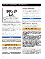
Fig. 2 Charger Installation
Provide Protection From Elements
Do Not Block Louvered Airways
NEMA 15 - 5R Grounded AC Receptacle
110 - 120 VAC. Dedicated 15 AMP Circuit
Locations outside the US and Canada: Reference
appropriate local electrical code and charger manu-
facturer recommendations for AC power requirements
NOTICE
NOTICE

