background image

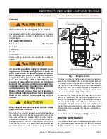
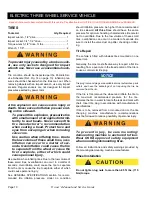
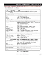
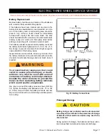
ELECTRIC THREE WHEEL SERVICE VEHICLE

Page 15

Owner’s Manual and Service Guide

Read all of manual to become familiar with this vehicle. Pay attention to all NOTICES, CAUTIONS,WARNINGS and DANGERS.

At Each Charging Cycle

To reduce the possibility of fire, never
attach a battery charger to a vehicle that is
to be unattended beyond the normal charg-
ing cycle. Overcharging could cause dam-
age to the vehicle batteries and result in
extreme overheating. The charger should be
checked after 24 hours and unplugged after
the charge cycle is complete.

Before charging the batteries, inspect all plugs/recepta-
cles of the battery charging system for dirt or debris. 

Charge the batteries after each days use. 

Monthly

Inspect all wiring for fraying, loose terminations,
corrosion or deterioration of insulation.

Check that the electrolyte level is correct and add
suitable water as required.

Clean the batteries and wire terminations.

Electrolyte Level and Water

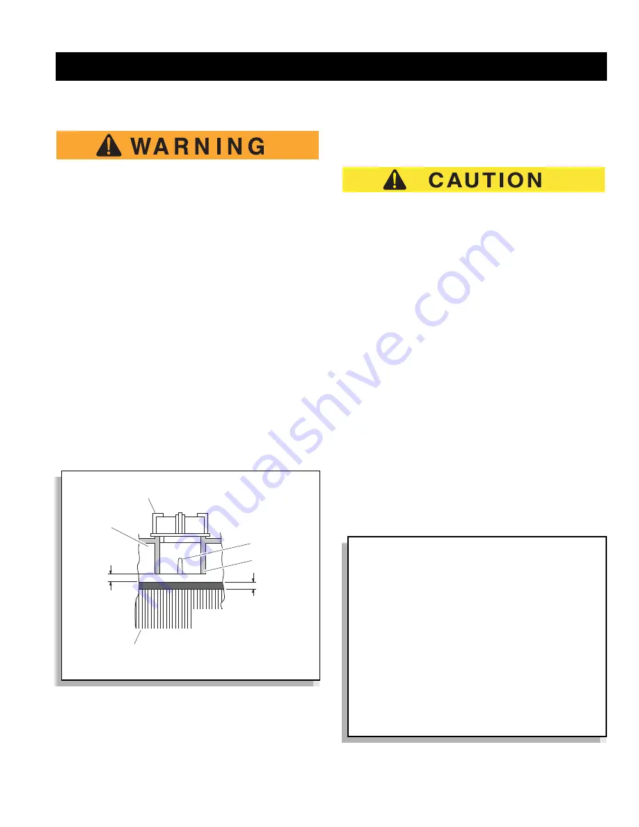
The correct level of the electrolyte is


1/2" (13 mm) above

the plates in each cell (Ref Fig. 15). 

This level will leave approximately 1/4" - 3/8" (6 - 10 mm)
of space between the electrolyte and the vent tube. The
electrolyte level is important since 

any portion

 of the

plates exposed to air will be ruined beyond repair. Of

equal importance is too much water which will result in
electrolyte being forced out of the battery due to gassing
and the increase in volume of the electrolyte that results
from the charging cycle.

Do not overfill batteries. The charging cycle will
expel electrolyte and result in component damage.

A battery being charged will ‘gas’ with the majority of the
gassing taking place at the end of the charging cycle.
This gas is hydrogen which is lighter than air. Water and
sulfuric acid droplets will be carried out of the battery
vents by the hydrogen gas; however, this loss is minimal.
If the battery electrolyte level is too high, the electrolyte
will block the vent tube and the gas will 

force

 it out of the

vent tube and battery cap. The water will evaporate but
the sulfuric acid will remain where it can damage vehicle
components and the storage facility floor. Sulfuric acid
loss will weaken the concentration of acid within the elec-
trolyte and reduce the life of the battery.

Over the life of the battery, a considerable amount of
water is consumed. It is important that the water used be
pure and free of contaminants that could reduce the life
of the battery by reducing the chemical reaction. The
water must be distilled or purified by an efficient filtration
system. Water that is not distilled should be analyzed
and if required, filtration installed to permit the water to
meet the requirements of the water purity table (Ref Fig.
16)

Fig. 15  Correct Electrolyte Level

Vent Cap

1/4" to 3/8"
(6 to 10 mm)

Plates

1/2" (13 mm)

Vent

Gas Vent

Expansion
Space

Electrolyte level should
be at least 1/2" (13 mm)
above the plates and
1/4" to 3/8" (6 to 10 mm)
below vent

Impurity

Parts Per

 Million

Color ............................................................................... Clear

Suspended...................................................................... Trace 

Total Solids .......................................................................100

Calcium & Magnesium Oxides...........................................40

Iron......................................................................................5

Ammonia.............................................................................8

Organic & Volatile Matter ...................................................50

Nitrites.................................................................................5

Nitrates ..............................................................................10

Chloride ..............................................................................5

Fig. 16  Water Purity Table

Summary of Contents for 612485

Page 1: ...A Textron Company ELECTRIC POWERED THREE WHEEL SERVICE VEHICLE ISSUED JULY 2009 OWNER S MANUAL AND SERVICE GUIDE 612485...

Page 2: ...l speeds encountered on a flat surface To pre vent loss of vehicle control and possible serious injury speeds should be limited to no more than the maximum speed on level ground See vehicle specificat...

Page 3: ...sed periodically by the CUSHMAN Division and therefore is subject to change without notice The CUSHMAN Division DISCLAIMS LIABLITY FOR ERRORS IN THIS MANUAL and the CUSHMAN Division SPECIFICALLY DISCL...

Page 4: ...self discharge varies depending on the ambient temperature and the age and condition of the batteries A fully charged battery will not freeze in winter temperatures unless the temperature falls below...

Page 5: ...Hour Meter 4 Horn 4 Accelerator and Brake Combination 4 Fig 6 Combination Accelerator and Brake Pedal 4 Headlights and Taillight 5 BEFORE ENTERING VEHICLE 5 OPERATING THE VEHICLE 5 STARTING THE VEHICL...

Page 6: ...15 Cleaning Batteries 16 Fig 17 Automatic Watering Gun 16 Fig 18 Preparing Acid Neutralizing Solution 16 Battery Replacement 17 Fig 19 Battery Connections 17 Prolonged Storage 17 Fig 20 Freezing Point...

Page 7: ...as personal transportation vehicles BE OPERATED ONLY BY PERSONS WITH VALID DRIVERS LICENSES AND IN ACCORDANCE WITH APPLICABLE STATE REQUIREMENTS This restriction is important to the SAFE USE AND OPERA...

Page 8: ...the safety of the vehicle GENERAL OPERATION Always use the vehicle in a responsible manner and maintain the vehicle in safe operating condition Always read and observe all warnings and operation instr...

Page 9: ...to recognize and protect themselves from potential situations that could result in severe personal injury or death and damage to the vehicle Use extreme caution and if unsure as to the potential for i...

Page 10: ...Owner s Manual and Service Guide SAFETY INFORMATION Page viii Read all of manual to become familiar with this vehicle Pay particular attention to all NOTICES CAUTIONS WARNINGS and DANGERS NOTES...

Page 11: ...ch affects capacity or safe operation or make any change not in accordance with the owner s manual without the manufacturer s prior written authori zation Where authorized modifications have been made...

Page 12: ...us experience 5 2 3 The user should include in the operators train ing program the following a instructional material provided by the manufac turer b emphasis on safety of passengers material loads ca...

Page 13: ...rakes It is advisable that all other personnel leave the elevator before a carrier is allowed to enter or exit 5 5 13 Avoid running over loose objects potholes and bumps 5 5 14 To negotiate turns redu...

Page 14: ...able cleaning fluids for cleaning parts j Properly ventilate the work area k Handle LP gas cylinders with care Physical dam age such as dents scrapes or gouges may danger ously weaken the tank and mak...

Page 15: ...ntilated minimum of 5 air exchanges per hour To reduce the chance of battery explosion that could result in severe injury or death never smoke around or charge batteries in an area that has open flame...

Page 16: ...er AC cord is equipped with a ground plug do not attempt to pull out cut or bend the ground plug If vehicle is to be charged with a non Original Equipment Manu facturer OEM charger refer to the instru...

Page 17: ...then plug the portable charger into the small connector of the charger distribution har ness Ref Fig 3 SERIAL PLATE LOCATION The plate with the serial and manufacturing numbers are located as shown R...

Page 18: ...d in a non congested area at low speed until the operator becomes more familiar with the vehicles characteristics Removing partial pressure from the foot pedal reduces the speed but does not engage th...

Page 19: ...ations allow Consid er the terrain traffic conditions and the environmental factors which effect the terrain and the ability to control the vehi cle Use extra care and reduced speed when driving on po...

Page 20: ...imum speed on level ground see GENERAL SPECIFICATIONS Limit speed by releasing the toe of the pedal and applying pressure to the heel of the pedal Severe damage to the drive train components due to ex...

Page 21: ...or the rear wheels Servicing that requires access to the underside of the vehicle should be accom plished by raising the front of the vehicle with a chain hoist attached to the front frame members Alw...

Page 22: ...ant level The rear axle is provided with a lubricant level check fill plug located on the bottom of the differential Unless leakage is evident the lubricant need only be replaced after five years Chec...

Page 23: ...ehicle Determine the braking performance of the vehicle by engaging the service brake release accelerator pedal only at a common point on a flat dry clean paved sur face while traveling at maximum spe...

Page 24: ...nds Overinflation could cause the tire to separate from the rim or cause the tire to explode either of which could cause personal injury See GENERAL SPECIFICATIONS section for recom mended tire inflat...

Page 25: ...pre serving the painted surfaces Do not use hot water strong soap or harsh chemical detergents Rubber parts should be cleaned with nonabrasive house hold cleaner Occasional cleaning and waxing with no...

Page 26: ...URES ARE IN FT LBS Nm BOLT SIZE Grade 2 1 4 5 16 3 8 7 16 1 2 9 16 5 8 3 4 7 8 1 Unless otherwise noted in text tighten all hardware in accordance with this chart This chart specifies lubricated torqu...

Page 27: ...RECEPTACLE Clean connections keep receptacles free of dirt and foreign matter ACCELERATOR Check for smooth movement DIRECTION SELECTOR Check attachment tighten if required STEERING AND LINKAGES Check...

Page 28: ...flushed with water Overfilling batteries may result in elec trolyte being expelled from the battery during the charge cycle Expelled elec trolyte may cause personal injury and damage to the vehicle a...

Page 29: ...o not overfill batteries The charging cycle will expel electrolyte and result in component damage A battery being charged will gas with the majority of the gassing taking place at the end of the charg...

Page 30: ...f the batteries To prevent battery damage be sure that all battery caps are tightly installed The correct cleaning technique is to spray the top and sides of the batteries with a solution of sodium bi...

Page 31: ...terminals Clean any corrosion from the battery terminals or the wire terminals with a solution of sodium bicarbonate baking soda and brush clean if required To prevent battery explosion that could res...

Page 32: ...attery charger is designed to fully charge the bat tery set If the batteries are severely deep cycled some automatic battery chargers contain an electronic module that may not activate and the battery...

Page 33: ...ell Ref Fig 21 This is performed by measuring the density of the electrolyte which is accomplished by measuring the specific gravity of the electrolyte The greater the concentration of sulfuric acid t...

Page 34: ...mperature was 70 F 21 C subtract four points 004 from the 1 250 to give a corrected reading of 1 246 Ref Fig 22 5 Test each cell and note the readings corrected to 80 F or 27 C A variation of fifty po...

Page 35: ...Page 21 GENERAL SPECIFICATIONS Owner s Manual and Service Guide GENERAL SPECIFICATIONS...

Page 36: ...LIGHTING HORN Standard Rear brake light horn TIRES Standard 4 80 x 8 Industrial Load Range B TIRE PRESSURE 60 psi 415 kPa WEIGHT without batteries 490 lbs 225 kg OPERATING CONTROLS INSTRUMENTATION Re...

Page 37: ...d Incline Specifications 77 5 in 197 cm 84 in 213 cm 29 5 in 75 cm 22 5 in 57 cm 78 in 198 cm 98 in 248 cm 21 5 in 55 cm 29 in 74 cm 17 5 in 44 cm 48 in 122 cm 48 in 122 cm RECOMMENDED MAXIMUM RAMP GR...

Page 38: ...anual and Service Guide GENERAL SPECIFICATIONS Fig 24 Vehicle Turning Clearance Diameter and Intersecting Aisle Clearance TURNING CLEARANCE DIAMETER 56 in 142 cm 56 in 142 cm INTERSECTING AISLE CLEARA...

Page 39: ...nts will eventually fail to perform properly as the result of normal use age wear or abuse It is virtually impossible to anticipate all possible compo nent failures or the manner in which each compone...

Page 40: ...n of Textron Inc 1451 Marvin Griffin Road Augusta Georgia USA 30906 3852 TO CONTACT US North America Technical Assistance Warranty Phone 1 800 774 3946 FAX 1 800 448 8124 Service Parts Phone 1 888 GET...

Reviews: