Page J-1
Repair and Service Manual
ELECTRICAL SYSTEM
Read all of Section B and this section before attempting any procedure. Pay particular attention to Notices, Cautions, Warnings and Dangers.
DIGITAL VOLT OHM METER
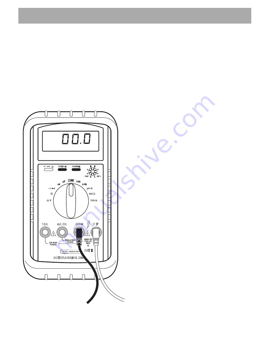
A typical DVOM (digital volt ohm meter) is shown (Ref.
Fig. 1 on Page J-1). A recommended model is available
through the Service Parts Department as P/N 27481-
G01. For the purpose of this section, the red probe (+)
and black probe (-) are used. Any DVOM may be used,
however the controls, displays, accuracy and features
may vary depending on the make and model. Always
follow the meter manufacturer’s recommendations and
instructions for the use and care of the meter.
Fig. 1 DVOM
TROUBLESHOOTING
In order to effectively troubleshoot the circuits that
include the horn, lighting, brake/turn signals and
gauges, the technician must be able to use the wiring
diagram and a DVOM.
The wiring diagram shows the path followed by voltage
or a signal from its origination point to its destination
(Ref. Fig. 2 on Page J-2). Each wire is indicated by
color.
The technician should use simple logic troubleshooting
in order to reduce the number of steps required to iso-
late the problem.
Example 1: If the vehicle will not start and none of the
lights function (or burn dimly) the battery should be
tested before trying to troubleshoot the lighting circuit.
Example 2: If a problem occurs in the lighting circuit that
results in only one of the headlights not working, there is
no reason to check battery wiring or the fuse since it is
obvious that voltage is present. Since bulbs will burn out
over time, the obvious place to start is at the headlight
that is not functioning. If power is present at the connec-
tor and the ground wiring is satisfactory, the only possi-
bilities that exist are a burned out bulb or a poor contact
between the connectors and the headlight.
If power is not present but the other headlight functions,
a wiring problem is indicated between the two head-
lights.
In some cases where battery voltage is expected, the
easiest way to test the circuit is to set the DVOM to DC
volts and place the negative (-) probe of the DVOM to
the negative battery terminal. Move the positive (+)
probe to each wire termination starting at the battery and
working out to the device that is not working. Be sure to
check both sides of all switches and fuses.
When no battery voltage is found, the problem lies
between the point where no voltage is detected and the
last place that voltage was detected. In circuits where no
voltage is expected, the same procedure may be used
except that the DVOM is set to continuity. Place the neg-
ative (-) probe on a wire terminal at the beginning of the
circuit and work towards the device that is not working
with the positive (+) probe. When continuity is no longer
indicated, a failed conductor or device is indicated.


