B
18
OPERATING PROCEDURES
Read all of SAFETY and this section before attempting any procedure. Pay particular attention to Notices, Cautions, Warnings and Dangers.
Owner’s Guide
UNDERSTAND THE CHARGER
When the charger is connected to the vehicle, the vehicle will not operate. When the charger is connected to the vehicle,
the charger will automatically turn on. The LED lights on the charger and the vehicle flash GREEN to indicate the charge
cycle has started.
When minimum voltage of 2 volts per cell (VPC) is reached, the charger output electric current will change from full elec-
tric current to trickle electric current. The length of charge time depends on how discharged the batteries are, the input
AC voltage and charger ambient temperatures.
The charger LED light will give a SHORT flash if the charge is less than 80%. The charger LED light will give a LONG
flash if the charge is more than 80%. SOLID GREEN indicates that the batteries are completely charged and you can dis-
connect the charger, but it is not necessary. The charger can stay connected to keep the batteries charged.
If a fault occurred during the charge cycle, the charger LED will quickly flash RED. The specified fault is indicated by the
number of RED flashes that occur, a pause, and the RED flashes repeat again. Errors are caused by different conditions.
Some errors need a person to correct the problem and then reset the charger. Disconnect the DC cord from the vehicle
to reset the charger.
If the AC voltage is interrupted and restored, the charger will automatically turn on again.
LED Operation Codes
•
SHORT GREEN FLASH = less than 80% of charge capacity
•
LONG GREEN FLASH = more than 80% of charge capacity
•
SOLID GREEN = 100% of charge capacity
•
RED FLASH = fault code
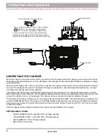
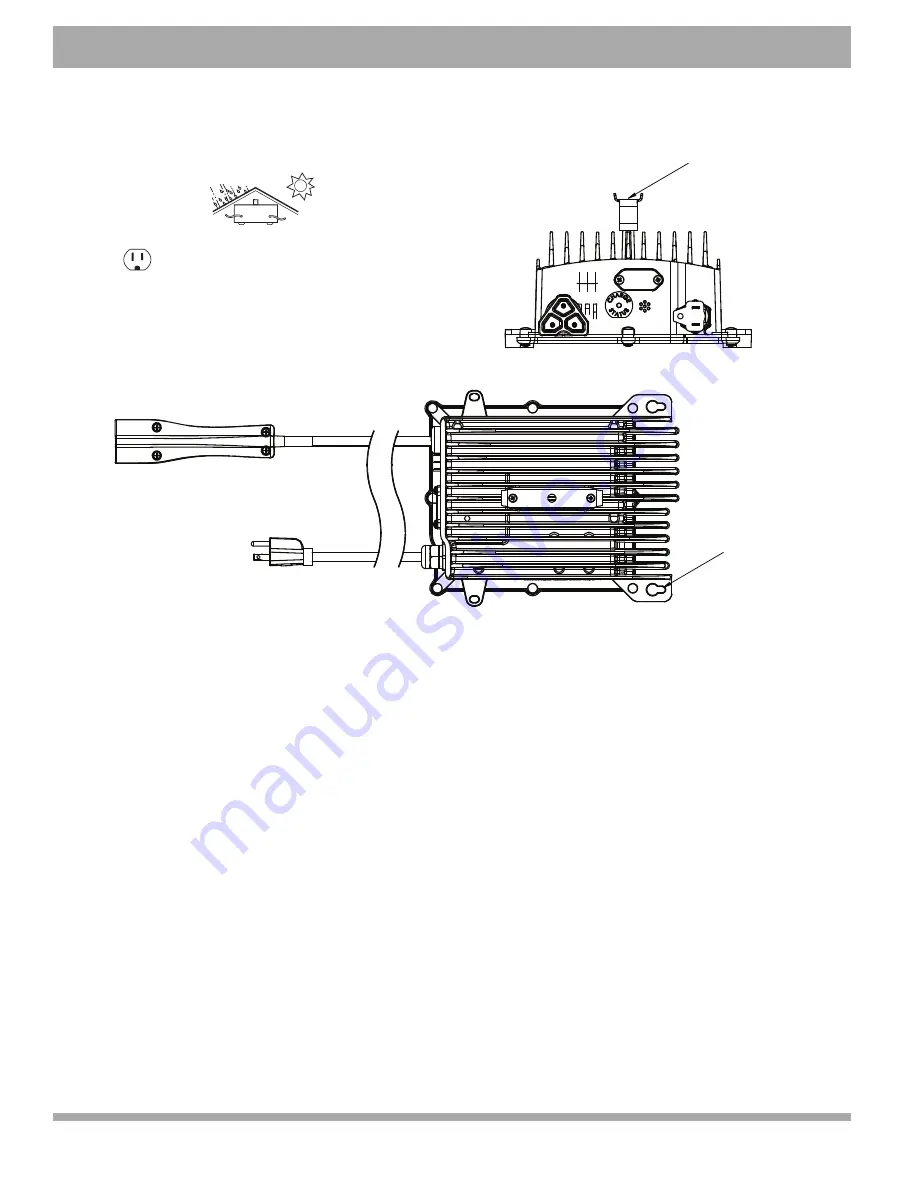
Provide Protection From Elements
Keep cooling fins clean and free of dirt and debris
NEMA 15 - 5R Grounded AC Receptacle
110 - 120 VAC. Dedicated 15 AMP Circuit
Locations outside the US and Canada: Reference
appropriate local electrical code and charger manu-
facturer recommendations for AC power requirements
Hanging Holes
Mounting Holes
Summary of Contents for Hauler 800XE
Page 1: ...OWNER S GUIDE 642988 B HAULER 800XE REVISED FEBRUARY 2016 ISSUED FEBRUARY 2015...
Page 61: ......
Page 62: ......

