Page F-10
Repair and Service Manual
B
ELECTRONIC SPEED CONTROL
Read all of Section B and this section before attempting any procedure. Pay particular attention to Notices, Cautions, Warnings and Dangers.
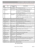
Fig. 11 J-1 Pin Connector Diagnostics
1
2
3
4
5
6
7
8
9
10
11
12
13
14
15
16
17
18
19
20
21
22
23
24
J1
1
2
3
4
5
6
J2
1
2
3
4
J3
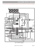
F2
Charger Interlock
Switch (Optional)
Walkaway
Fuse
(20A)
B+
+
+
M-
B-
-
-
F1
F
R
N
Key Switch
Forward
Reverse
Mode (M1,M2)
Reverse Alarm
Pedal Interlock
Brake Light Relay
Logic Enable
Pot High
Throttle
Pot
Pot Low
Pot Wiper
Ground
LED Driver
Fuse Sense
Walk Away Return
Walk Away Driver
KSI
Logic Power
Main Contactor
Summary of Contents for Shuttle 2
Page 6: ...Page iv Repair and Service Manual NOTES TABLE OF CONTENTS ...
Page 195: ......


