MHW 0012 – DK 1713 | Version 004 – 20/04/2020 | custo med GmbH
2
Resting and Stress ECG
Hardware, description of device for custo cardio 400 BT and custo cardio 400 accu
[2] Resting and Stress ECG Hardware, custo cardio 400 devices |
page 10
2.4.2
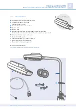
custo cardio 400 accu and custo move extension arm
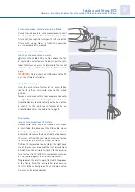
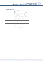
custo move operating elements
Bracket for custo cardio 400 accu
with safety bar
Anti-rotation lock for fixing the extension arm,
open during operation, swivel range 270°
USB connection
Power cable
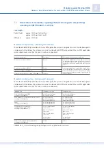
Mount the cable hook
(for holding the patient leads)
Attach the cable hook to the custo move extension
arm in the desired position with the screws supplied.
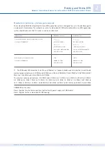
Mounting the fixture for custo move extension arm
The fixture for the custo move extension arm is inclu-
ded as standard in the custo easy plus equipment cart.
For older versions of the custo easy plus equipment
cart, the fixture for custo move must be ordered se-
parately. custo move may only be mounted in the new
fixture (from 2020 with radial groove, see ).
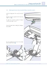
Screw the fixture onto the equipment cart with the
groove facing backwards. Use the supplied screws.
Then attach the cover plate. To do this, slide the
round opening of the cover plate over the fixture so
that the column of the equipment cart is closed at the
top.
Then insert the inset for the custo move extensi-
on arm into the fixture from above. The groove of the
inset is also aligned to the rear, corresponding to the
groove in the fixture.
Insert custo move extension arm into the fixture
Insert the USB and power cable of the custo move ex-
tension arm into the column of the equipment cart via
the opening of the fixture. Align the custo move ex-
tension arm so that the anti-rotation lock is located
above the groove of the fixture and inset. Insert the
custo move extension arm. The anti-rotation lock is
located on the transverse groove of the holder.
Fixture for
extension arm
Equipment cart
custo easy plus
Inset, groove
to the back!
Cover plate

