background image

INTRODUCTION

KPM216H

1

MANUAL CONTENTS

In addition to the Introduction which includes a description of the explanatory notes used in the
manual, general safety information, how to unpack the printer and a brief description of the
printer including its basic features, this manual is organized as follows:
Chapter 1:

Contains the information required for correct printer installation and its proper

use

Chapter 2:

Contains information on interface specifications

Chapter 3:

Contains a description of the printer command set

Chapter 4:

Contains Technical Specifications of the printer

Chapter 5:

Contains the character sets (fonts) used by the printer

EXPLANATORY NOTES USED IN THIS MANUAL

N.B.

Gives important information or suggestions relative to the use of the printer.

WARNING

Information marked with this symbol must be carefully followed to guard against
damaging the printer.

DANGER

Information marked with this symbol must be carefully followed to guard against
operator injury or damage.

GENERAL SAFETY INFORMATION

Read and keep the instructions which follow.

Follow all warnings and instructions indicated on the printer.

Before cleaning the printer, disconnect the power supply.

Clean the printer with a damp cloth. Do not use liquid or spray products.

Do not operate the printer near water.

Do not use the printer on unstable surfaces that might cause it to fall and be seriously
damaged.

Be careful when installing because this piece of equipment is suitable for mounting on
concrete or other noncombustibile surface only (self-extinguishing grade 94-V1 min.).

Only use the printer on hard surfaces and in environments that guarantee proper
ventilation.

Make sure the printer is placed in such a way as to avoid damage to its wiring.

Use the type of electrical power supply indicated on the printer label. If in doubt, contact
your retailer.

Using a power supply of SELV type to feed the printer.

Do not block the ventilation openings.

Summary of Contents for KPM 216 H

Page 1: ...KPM216H Thermal printer for information kiosks and ATMs KPM 216 H 210 216mm 8 5 User Manual www custom it...

Page 2: ...on regarding any errors found in it or suggestions on how it could be improved are appreciated Since products are subject to continuous check and improvement CUSTOM ENGINEERING SPA reserves the right...

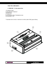
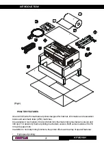
Page 3: ...216H Front external view 1 Printing head set 2 Opening lever of head set 3 Roller cover 4 Paper exit 1 5 Lock Unlock button of motorization cover 6 Motorization cover 1 Available in two versions horiz...

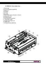
Page 4: ...aper feed guides adjustable 3 Status led 4 Feed key 5 Print key 6 Reset key 7 External near paper end sensor connector 8 Motorization cover 9 Printing head set 10 Opening lever of head set 11 Tilting...

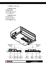
Page 5: ...l KPM216H P model C KPM216H Under view KPM216H U model 1 Serial connector 2 USB connector 3 Power supply connector 4 Power supply fuse KPM216H P model 5 Serial connector 6 Centronics connector 7 Power...

Page 6: ...KPM216H Blank page...

Page 7: ...1 6 4 Paper jam 1 10 1 6 5 Cleaning the print head 1 13 1 6 6 Cleaning the ejector rollers 1 15 1 7 TICKET CHARACTERISTICS 1 16 1 7 1 Ticket characteristics 1 16 2 INTERFACES 2 1 RS232 SERIAL 2 1 2 2...

Page 8: ...TABLE OF CONTENTS KPM216H ii Blank page...

Page 9: ...he printer DANGER Information marked with this symbol must be carefully followed to guard against operator injury or damage GENERAL SAFETY INFORMATION Read and keep the instructions which follow Follo...

Page 10: ...outer casing damaged F Printer performance is poor G The printer is not functioning UNPACKING THE PRINTER Remove the printer from its carton being careful not to damage the packing material so that i...

Page 11: ...and automatic teller ATM machines It is available in two models 204 dpi 8 dots mm thermal printing mechanism version and 300 dpi 11 8 dots mm thermal printing mechanism version Both versions utilize 2...

Page 12: ...The printer fig 2 is comprised of a metal frame printing mechanism a cutter and an ejector Located on the keypad are the following keys LINE FEED 1 FORM FEED 2 Reset 3 and status LED 4 LINE FEED key...

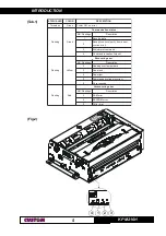
Page 13: ...R r o r r e n u r r e v o 3 d n a m m o c t e r p r e t n i s i M 4 t u o e m i t n o i t p e c e r d n a m m o C g n i h s a l F w o l l e Y r o r r e g n i r e v o c e R s g n i h s a l F R N n o i...

Page 14: ...INTRODUCTION KPM216H 6 Blank page...

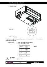
Page 15: ...ipped with an external power supply outlet see Fig 1 1 The connector pin configuration is as follows Model no type Header Molex 39 30 0060 Vertical Housing Molex 39 01 2065 o N n i P l a n g i S 1 V 4...

Page 16: ...i P d e t c e n n o c t o N 3 o n n i P D E R 4 o n n i P K C A L B 5 o n n i P d e t c e n n o c t o N 6 o n n i P K C A L B Note The red cable is for 24 Vdc The black cable is for signal ground 1 2...

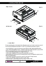
Page 17: ...UTTER TEST the message OK appears if functioning and NOT OK if faulty under HEAD VOLTAGE is given the voltage of the head under HEAD TEMPERATURE is given the temperature of the head under PWM EJECTER...

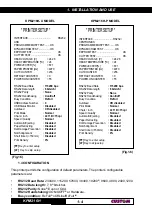
Page 18: ...Status Monitor Disabled Autofeed CR disabled Print Mode Normal Chars inch A 11 B 15 cpi Speed Quality Normal Automatic Ejecting Disabled Paper Retracting Disabled Dot Damage Prevention Disabled Notch...

Page 19: ...oth in Off Line status and the buffer is full or only if the reception buffer is full 3 N B This parameter is displayed if the printer has an USB interface The Status Monitor is an additional printing...

Page 20: ...AL DUMP This function is used to display the characters received from the communications port the printer prints out both the hexadecimal code received as well as the corresponding ASCII code Once the...

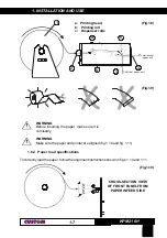
Page 21: ...3 3 c b a a Printing head b Printing roll c Dispenser rolls WARNING Before inserting the paper make sure it is cut cleanly WARNING Make sure the paper and printer are aligned fig 1 10 and fig 1 11 1 6...

Page 22: ...1 INSTALLATION AND USE KPM216H 8 1 Paper direction axis max 1 max 1 WARNING MOVING PARTS Fig 1 11 WARNING The roll must be perfectly aligned with the printer fig 1 11 The maximum play allowed is 1...

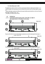
Page 23: ...he paper guides according to the paper width desired use the notches on the front as a guide as shown in fig 1 12 Re tighten the fastening screws d ATTENTION Assemble the lateral paper guides so that...

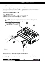
Page 24: ...ejected If this does not solve the problem proceed as follows Paper jammed on ejector see fig 1 15 1 Lift the roller cover 1 2 Remove any pieces of paper present in the ejector rollers 2 3 Remove any...

Page 25: ...KPM216H 11 1 1 2 1 2 Open 8 the lateral cover 1 rotating the lock unlock button 2 with the screwdriver or coin see fig 1 17 8 N B To close lateral cover once reassembled it push the the lock unlock bu...

Page 26: ...the cover before pulling up the cutter Extract the cover unit pulling from the bottom to the outside and then lifting up to release the two slots see fig 1 18 4 Pulling up the cutter as shown in the f...

Page 27: ...Do not perform any operation inside the printer immediately after printing because the head and motor tend to become very hot The printer must be turned off when the printing head unit is removed Turn...

Page 28: ...arrow 1 2 Clean the printing head heating line 1 using a non abrasive cloth moistened with denatured alcohol see fig 1 21 3 Lower the cover 1 to close and pressing 2 in the exact point indicated from...

Page 29: ...The printer must be turned off during cleaning operations Caution during cleaning operations to tilting paper holder 3 Turn off the printer and proceed as follows 1 Lift up the roller cover 1 as show...

Page 30: ...CKET CHARACTERISTICS 1 7 1 Ticket characteristics It s possible to use paper with alignment mark The figure 1 25 shows paper with alignment mark fac simile the notch distance in mm from the beginning...

Page 31: ...t a D e n o i z a u d i v i d n I h g i h l e v e l 2 D X T T U O a t a d t i m s n a r T 3 D X R N I a t a d e v i e c e R 4 C N d e t c e n n o c t o N 5 D N G d n u o r G l a n g i S 6 R S D T U O...

Page 32: ...3 4 2 1 RXD SIGNAL GND RXD DCD CTS DSR 8 9 7 5 6 3 4 2 1 TXD 1 2 3 4 5 6 7 8 9 10 11 12 13 14 15 16 17 18 19 20 21 22 23 24 25 KPM216H PC KPM216H PC The diagrams below illustrate a sample connection...

Page 33: ...and Fault respond to the logic of functioning of the Centronics parallel port The signal Ticket Presence is high if the ticket is present on the mouth of exit the signal Near paper end is high when t...

Page 34: ...INTERFACES KPM216H 4 2 1 2 3 4 5 9 8 7 6 SERIAL 13 1 25 14 PARALLEL For the parallel connector the connection between printer and Personal Computer must be made with a 25 pin to pin connector Fig 2 5...

Page 35: ...e n m t x y are optional parameters that can have different values 3 2 1 ESC POS Emulation The following table lists all the commands for function management in ESC POS Emulation of the printer The co...

Page 36: ...p d e e f d n a t n i r P H n L n C S E H n L n C 5 B 1 n o i t i s o p t n i r p e v i t a l e r t e S n a C S E n 1 6 B 1 n o i t a c i f i t s u j t c e l e S n d C S E n 4 6 B 1 s e n i l n r e p...

Page 37: ...a r T n w S G n 7 7 D 1 r a b f o t n e m e g r a l n e e d i s l a t n o z i r o h t c e l e S e d o c n S G n C 7 D 1 y t i s n e d t n i r p t e S H y L x H x 0 D S G L y H y L x H x 0 D D 1 L y e...

Page 38: ...executes print buffer full printing and horizontal tab process ing from the beginning of the next line Default Reference Example F L Name Print and line feed Format ASCII LF Hex 0A Decimal 10 Descript...

Page 39: ...e status transmission Format ASCII DLE EOT n Hex 10 04 n Decimal 16 4 n Range 1 n 4 n 17 n 20 Description Transmits the selected printer status specified by n in real time according to the following p...

Page 40: ...e f t n s i r e p a P n O 8 0 8 n o t t u b D E E F E N I L y b d e d e e f s i r e p a P 4 D E V R E S E R 5 f f O 0 0 0 t n e s e r p r e p a P n O 0 2 2 3 d n e r e p a p o t e u d p o t s g n i t...

Page 41: ...E S E R 4 D E V R E S E R 5 f f O 0 0 0 t n e s e r p r e p a P n O 0 2 2 3 t n e s b a r e p a P 6 D E V R E S E R 7 D E V R E S E R n 20 FULL status 6 bytes 1 Byte 0x10 DLE 2 byte 0x0F 3 byte Paper...

Page 42: ...e k F F n O 0 4 4 6 d e s s e r p y e k F F 7 D E V R E S E R 5 byte Recoverable error Status t i B n O f f O x e H l a m i c e D n u F n o i t c 0 f f O 0 0 0 k o e r u t a r e p m e t d a e H n O 1...

Page 43: ...Notes Sets the print position to the beginning of the line However this command does not clear the receive buffer Default Reference Example n P S C S E Name Set right side character spacing Format AS...

Page 44: ...3 1 4 2 x 0 1 1 d e n i f e d n U 2 d e n i f e d n U 3 f f O 0 0 0 d e t c e l e s t o n e d o m d e d n a p x E n O 8 0 8 d e t c e l e s e d o m d e d n a p x E 4 f f O 0 0 0 d e t c e l e s t o n...

Page 45: ...quent characters are to be printed The distance from the beginning of the line to the print position is nL nH 256 vertical or horizontal motion unit inches Notes Settings outside the specified printab...

Page 46: ...cifies the final code X specifies the number of dots in the horizontal direction Notes The allowable character code range is fromASCII 20H 32 to 3FH 63 32 characters It is possible to define multiple...

Page 47: ...nt position to nL nH x 256 x horizontal or vertical motion unit Notes When the starting position is specified by N motion unit to the bottom nL nH x 256 N When the starting position is specified by N...

Page 48: ...rted characters When underline mode is turned off by setting the value of n to 0 or 48 the data which follows is not underlined Underline mode can also be turned on or off by using ESC Note however th...

Page 49: ...nimum vertical movement amount In standard mode the vertical motion unit is used Default n 64 Reference ESC 0 ESC 2 GS P or GS D0 Example n 4 C S E Name Set reset italic mode Format ASCII ESC 4 n Hex...

Page 50: ...n vertical or horizontal motion unit inches Notes After printing has been completed this command sets the print starting position to the beginning of the line The horizontal and vertical motion units...

Page 51: ...the starting position is specified by n motion units to the right nL nH 256 n When the starting position is specified by n motion units to the left negative direction use the complement of 65536 nL nH...

Page 52: ...ints the data in the print buffer and feeds the paper n rows Notes Sets the print starting position at the beginning of the line The maximum paper feed amount is 254 rows Even if a paper feed amount o...

Page 53: ...C v Hex 1B 76 Decimal 27 118 Description When this command is received transmit the current status of the paper sensor The status to be transmitted is shown in the table below t i B n O f f O x e H l...

Page 54: ...3 B t n o F Default n 0 Reference ESC Example L y H y L x H x n C S E Name Print graphic Format ASCII ESC n xH xL yH yL Hex 1B FA n xH xL yH yL Decimal 27 250 n xH xL yH yL Range 0 n 1 0 xH xL yH yL 2...

Page 55: ...send 1BH FAH 00H 00H 64H 00H C7H E C A F R E T N I L A I R E S H T I W Y L N O H n L n C S E Name Transmit graphic page to communication port Format ASCII ESC nL nH Hex 1B FB nL nH Decimal 27 251 nL...

Page 56: ...of data bytes received is nL nH 256 2 Each word is first received as MSByte and then as LSByte If nL nH 256 is greater than 32768 the data which follows is pro cessed as normal data The flash bank di...

Page 57: ...S x e H l a m i c e D h t d i W 0 0 0 l a m r o n 1 0 1 6 1 2 x 2 h t d i w 0 2 2 3 x 3 h t d i w 3 0 3 8 4 x 4 h t d i w 4 0 4 4 6 x 5 h t d i w 5 0 5 0 8 x 6 h t d i w 6 0 6 6 9 x 7 h t d i w 7 0 7...

Page 58: ...command does not affect white space between lines White black reverse mode has a higher priority than underline mode Even if underline mode is on it will be disabled but not cancelled when white black...

Page 59: ...a r a h c 4 n o i s r e v M O R n o s d n e p e D n 2 Type ID t i B n O f f O x e H l a m i c e D n o i t c n u F 0 f f O 0 0 0 d e t r o p p u s t o n s e d o c r e t c a r a h c e t y b 2 1 f f O 0...

Page 60: ...n unit are specified by GS P or GS D0 Changing the horizontal or vertical motion unit does not affect the current left margin The GS P or GS D0 command can change the horizontal and vertical motion un...

Page 61: ...e ESC J GS L GS W GS D0 Example m V S G n m V S G Name Select cut mode Format ASCII GS V m Hex 1D 56 m Decimal 29 86 m ASCII GS V m n Hex 1D 56 m n Decimal 1D 86 m n Decimal 29 86 m n Range m 0 48 m 6...

Page 62: ...otion units are specified by GS P or GS D0 Changing the horizontal or vertical motion unit does not affect the current left margin The GS P or GS D0 command can change the horizontal and vertical moti...

Page 63: ...0 0 0 f f o r o t o m r e t t i m E n O 0 2 2 3 n o r o t o m r e t t i m E 6 f f O 0 0 0 r o r r e t o N n O 0 4 4 6 r o r r E 7 f f O 0 0 0 e t u o r r e p a p e e r F n O 0 8 8 2 1 m a j r e p a P...

Page 64: ...mal 29 104 n Range 1 n 255 Description Sets the height of the bar code n specifies the number of vertical dots Notes Default n 162 20 25 mm Reference GS k Example L U N k d 1 d m k S G n d 1 d n m k S...

Page 65: ...2 1 E D O C 2 n 5 5 2 0 d 7 2 1 0 9 2 3 E D O C 8 n 9 8 4 d 7 5 Notes If d is outside of the specified range the printer prints the following message BAR CODE GENERATOR IS NOT OK and processes the da...

Page 66: ...I character n as a control character 00H to 1FH and 7FH When CODE128 is used When using CODE128 in this printer please note the following re garding data transmission The top part of the bar code data...

Page 67: ...e p a p r a e N t n e s e r p t o n r e p a P 3 2 f f O 0 0 0 r o s n e s d n e r e p a P t n e s e r p r e p a P n O C 0 2 1 r o s n e s d n e r e p a P t n e s e r p t o n r e p a P 4 D E V R E S E...

Page 68: ...ASCII GS n Hex 1D 7C n Decimal 29 124 n Range 0 n 8 48 n 56 Description Sets printing density n specifies printing density as follows n y t i s n e d g n i t n i r P 8 4 0 0 5 9 4 1 5 7 3 0 5 2 5 2 1...

Page 69: ...direction In standard mode the following commands use x or y regardless of character rotation upside down or 90 clockwise rotation Commands using x GS L GS W Commands using y ESC J This command does...

Page 70: ...compose the required status the status sent in automatic from the printer will be so composed as follows 1 Byte 0x10 DLE 2 Byte n Next byte depends how many bits are active in n Reference DLE EOT n Ex...

Page 71: ...of length cm of printed paper Format ASCII GS Hex 1D E3 Decimal 29 227 Description Reading of length cm of printed paper The command return a string pointing out how much paper is printed for example...

Page 72: ...Description This command sets the limit after which is pointed out the virtual paper end Notes The calculation limit of the near paper end is in centimetres This value is expressed as nH x 256 nL Def...

Page 73: ...n Decimal 29 240 n Range 0 n 2 Description Sets printing speed n specifies the printing speed as follows n r P i d e e p s g n i t n 0 w o L 1 l a m r o N 2 h g i H Notes Printing speed reverts to th...

Page 74: ...ticket at cut Notes Reference 1D F6 Example S F A 1 4 1 0 1 8 1 Name Hardware reset Format ASCII FS 18 10 14 1A Hex 1C C0 18 10 14 1A Decimal 28 192 24 16 20 26 Description When this command is receiv...

Page 75: ...l l o r l a n r e t x E m m 0 8 1 x a m 1 e p y t e r o C c i t s a l p r o d r a o b d r a C s r o s n e S k c a l b d n e r e p a p r a e N d a o l o t u A e r u t a r e p m e t d a e H t e k c i T...

Page 76: ...l o r r e p a p t u o h t i w g K 9 4 n o i t a l u m E S O P C S E M T h t g n e l t e k c i t e l b a t n i r p m u m i n i M m m 0 6 1 3 y t i s n e d r e t c a r a h C i p c 1 1 i p c 5 1 i p c 0...

Page 77: ...c i T r e v o c n o i t a z i r o t o m e d o m g n i t n i r P 0 7 2 0 8 1 0 9 t h g i a r t S t a m r o f g n i t n i r P e s r e v e r e c a f d l o b 8 o t 1 m o r f h t d i W t h g i e H c i l a...

Page 78: ...E e r u t a r e p m e t g n i t a r e p O C 0 5 C 0 y t i d i m u h e v i t a l e R n o i t a s n e d n o c o w 5 8 0 1 y t i d i m u h e r u t a r e p m e t e g a r o t S 0 9 0 1 C 0 7 C 0 2 S N O I...

Page 79: ...PECIFICATIONS KPM216H 5 4 127 218 212 Paper input 188 Paper input Vertical paper output Horizontal paper output 11 45 2 5 1 75 35 5 2 5 83 5 156 2 5 8 Fig 4 2 Right side view Dx Fig 4 3 Top view Fig 4...

Page 80: ...4 TECHNICAL SPECIFICATIONS KPM216H 6 4 110 164 4 271 2 100 WARNING MOVING PARTS Left side view Sx with cover open Fig 4 5 Front view with cover open Fig 4 6...

Page 81: ...ATIONS KPM216H 7 4 1 2 2 1 Paper outfeed direction In the following figures is showed the printer paper input 1 and paper output 2 in the fig 4 8 is illustrated the optional model with vertical paper...

Page 82: ...4 TECHNICAL SPECIFICATIONS KPM216H 8 4 Blank page...

Page 83: ...he 204 dpi 11 15 and 20 cpi and 300 dpi 17 23 and 30 cpi models which may be accessed through programming section 1 2 or control characters section 3 2 Each of these fonts offers the following code ta...

Page 84: ...5 CHARACTER SETS KPM216H 2 5 Blank page...

Page 85: ...l o v t u p t u O V 4 2 t n e r r u c t u p t u O x a M n i M A 0 A 5 9 y c n e i c i f f E n i M 8 7 s n o i t a c i f i c e p S t u p n I e g a t l o v t u p n I V 5 1 1 V 0 3 2 t n e r r u C A 8 5...

Page 86: ...be turned off during maintenance operations N B Check periodically belt condition which should not show any cracks wear and tear marks that could negatively affect printer performance Turn off the pr...

Page 87: ...S AND SPARE PARTS KPM216H 3 A 2 Remove the belt between the two pulleys from its seating as shown in fig A 2 3 Replace the belt and place it again between the two pulleys in its seating as shown in fi...

Page 88: ...the internal bottom side of the printer and then follow maintenance operations described into paragraph 1 6 4 relevant to paper jam lift the printing head 1 remove the lateral cover 2 lift up the cut...

Reviews: