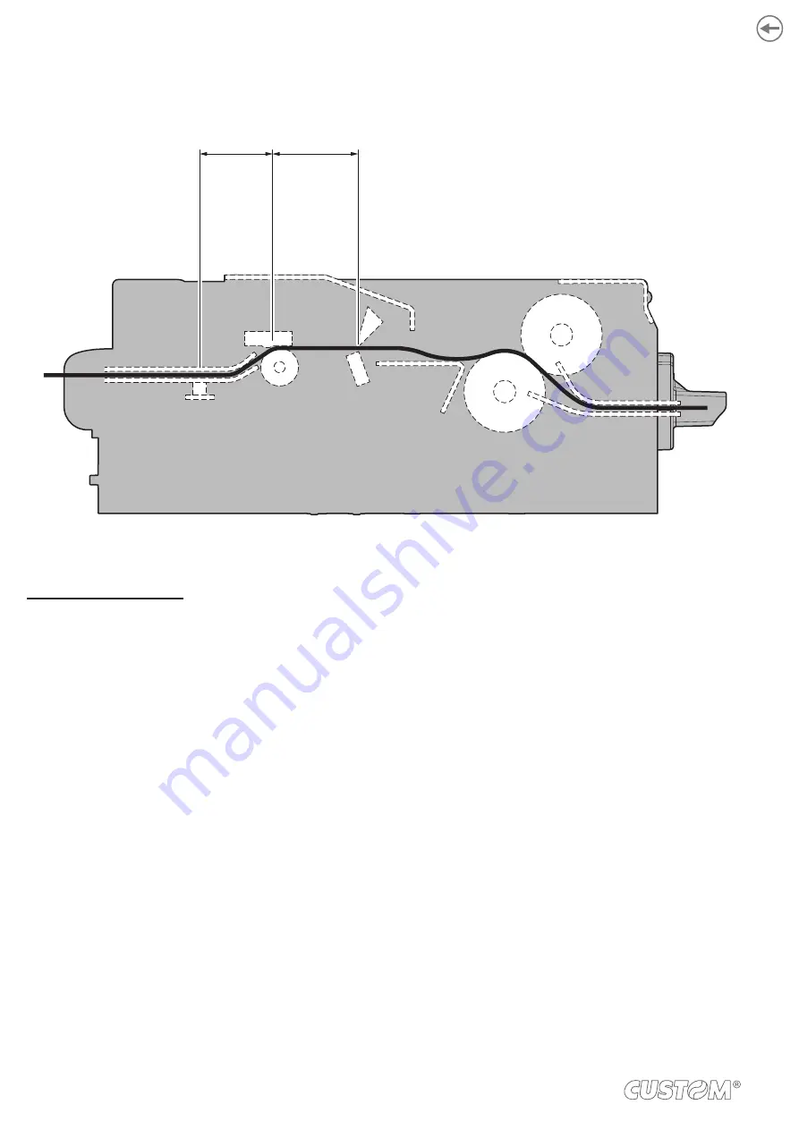
The following igure shows a section of the device with the paper path and the distances (expressed in millimetres) between
the alignment sensor, the printhead and the autocutter (cutting line).
Pri
n
th
e
a
d
N
o
tch
/B.
Ma
rk
se
n
so
r
25.5
Au
to
cu
tt
e
r
30
CUSTOM/POS emulation
To deine the alignment point you need to set the printer parameters that compose the numerical value of the “Black Mark
Distance” parameter. (see
For example, to set a black mark distance of 15 mm between the black mark and the alignment point, the parameters must
be set on the following values:
Black Mark Distance sign
: +
Black Mark Distance [mm x 10]
: 1
Black Mark Distance [mm x 1]
: 5
Black Mark Distance [mm x .1]
: 0
The “Black Mark Distance” parameter, may be modiied as described in
.
72
Summary of Contents for KPM216HIII
Page 1: ...USER MANUAL KPM216HIII ...
Page 2: ......
Page 4: ......
Page 6: ......
Page 10: ...10 ...
Page 12: ...12 ...
Page 22: ...22 ...
Page 66: ...66 ...
Page 74: ...74 ...
Page 93: ...127 140 5 140 5 74 8 147 4 83 30 5 196 24 5 5 24 5 5 159 48 270 1 6 16 5 16 5 12 5 12 5 12 93 ...
Page 100: ...100 ...
Page 102: ...102 ...


