6
6
1
1
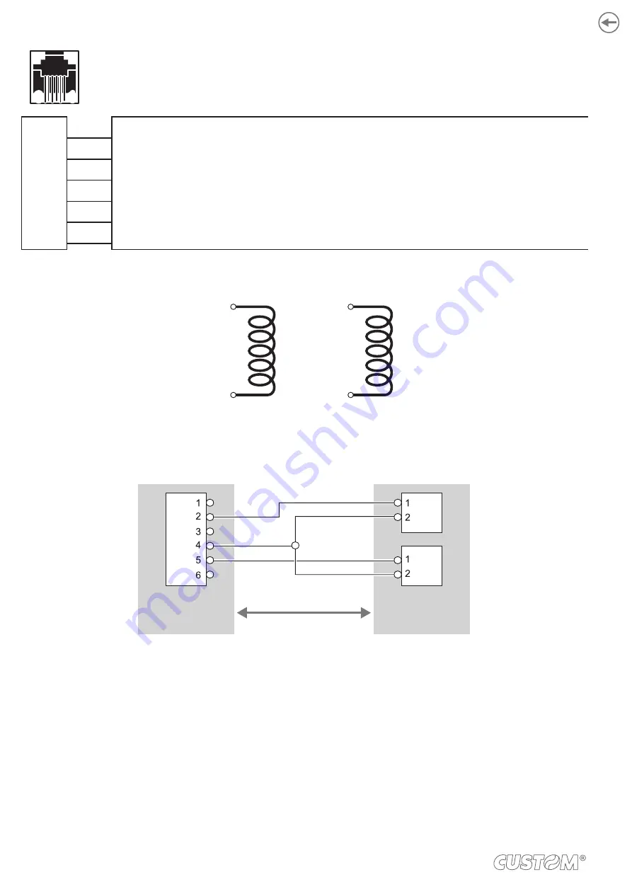
DRAWER CONNECTOR
Female RJ12 connector
J11
1 GND
2 CASS1
3 IN-CASS
4 +24VT
5 CASS2
6 GND
The solenoid of the drawer 1 must be connected from Pin 2 to Pin 4 on the drawer connector.
The solenoid of the drawer 2 must be connected from Pin 4 to Pin 5 on the drawer connector.
PIN 2
D
R
A
W
ER
1
PIN 4
PIN 4
D
R
A
W
ER
2
PIN 5
DEVICE > CASH DRAWER (optional) connection.
Use an optional adapter cable RJ12-Jack to connect the device to a cash drawer. Refer to the picture below for the con-
nector pin signals.
DEVICE
JAC
K
R
J1
2
CASH
DRAWER
SOL1
SOL2
+24Vdc
(+)
(-)
JAC
K
(+)
(-)
24
Summary of Contents for P3
Page 1: ...USER MANUAL P3 ...
Page 2: ......
Page 4: ......
Page 6: ......
Page 10: ...10 ...
Page 18: ...18 ...
Page 26: ...26 ...
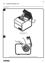
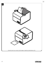
Page 30: ...Close the device cover and wait until the paper is loaded and automatically cut off 3 30 ...
Page 40: ...40 ...
Page 50: ...50 ...
Page 60: ...60 ...
Page 62: ...62 ...
Page 64: ...64 ...
Page 66: ...66 ...
Page 67: ......


