3.4 Pinout
4
1
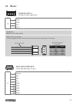
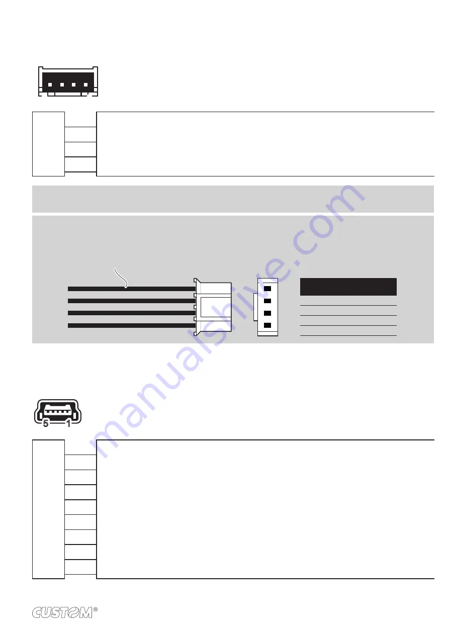
POWER SUPPLY
JST male connector (S4B-PH-K-S)
J8
1 GND
2 GND
3 +VP
4 +VCC
ATTENTION:
Respect power supply polarity.
NOTE: Power supply cable
The following igure shows the connector pinout of the power supply cable for the device:
Female JST connector
series PHR-4
+VCC
Red
4
+VP
Orange
3
GND
Black
2
Segnal
Cable
color
PIN
GND
Black
1
1
4
Power supply cable
5
1
MINI USB INTERFACE
Female MINI USB type B connector
J1
1 VPLUG
2 D0-
3 D0+
4 n.c.
5 GND
SH1 GND
SH2 GND
SH3 GND
SH4 GND
23
Summary of Contents for PLUS2
Page 1: ...CUSTOM S p A USER MANUAL PLUS2 ...
Page 2: ......
Page 4: ......
Page 5: ...MANUAL For details on the commands refer to the manual with code 77200000002100 ...
Page 6: ......
Page 10: ...10 ...
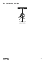
Page 15: ...2 5 Key functions standby advance the paper preset length STANDBY Fast push 15 ...
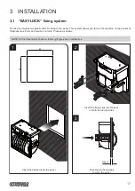
Page 18: ...4 To remove the fixing clips lift the lever shown in figure with a small screwdriver 18 ...
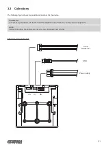
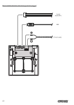
Page 22: ...Model with the 8 42 Vdc extended range module plugged USB Serial RS232 TTL Power supply 22 ...
Page 28: ...28 ...
Page 38: ...38 ...
Page 56: ...56 ...
Page 61: ...Device dimensions with the frame assembled 119 max 46 5 17 4 123 2 112x112 119 RS232 TTL 61 ...
Page 62: ...62 ...

