Installation Instructions
-
Page 2
11
-
2017
Custom Dynamics® Smart Signal Stabilizer
™
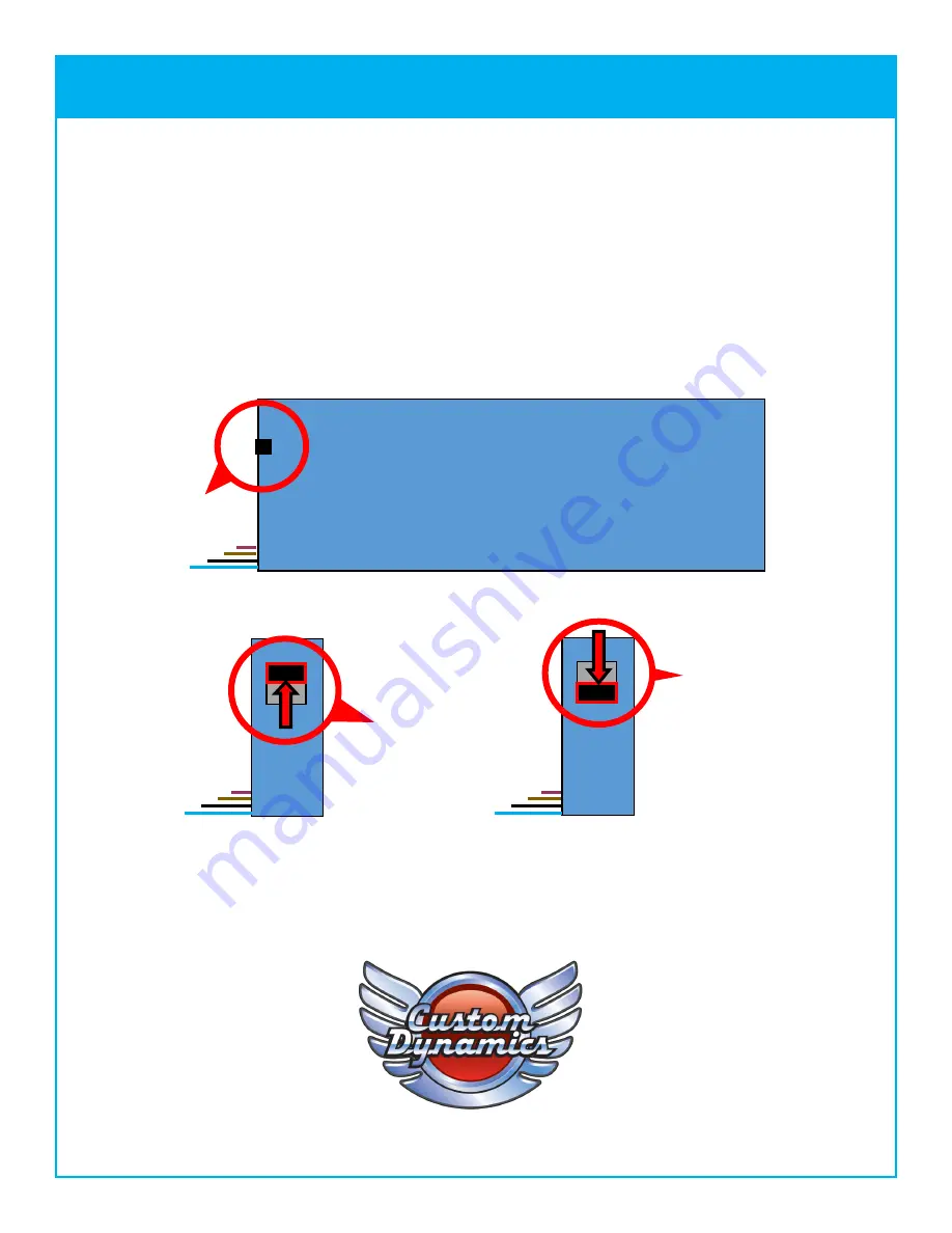
Load Switch Diagram
Custom Dynamics®
Load Switch
Wires
Up Position:
(Away from wires)
Normal Load
Down Position:
(Toward wires)
High Load
7.
Turn key on and test turn signals, running lights, and brake lights for proper operation. If you experience fast
flashing from the turn signals, turn the key off, move the recessed switch on the side of the stabilizer to the
“
high
”
position (see diagram below). You can use a small screwdriver to move the switch to the down position. Repeat
steps 6 & 7.
8.
Test the lights for proper operation for running lights, brake lights and turn signals before riding.
9.
Test Alarm for proper operation, if equipped.
EVERYTHING to Light Up Your Ride®


