background image

Spur Gear Assembly

Spur Gear Assembly

Spur Gear Assembly

Spur Gear Assembly

Spur Gear Assembly

5245     Qty 1
5-40 Locknut

1:1

-Parts for
 Bag G

1:1

2228     Qty 1
Spacer

2228             Qty 1
Slipper Eliminator

4881               Qty 1
81T 48P Spur Gear

5252                 Qty 2
4-40 x 1/4 BH Screw

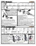
- Press the 2228 Slipper Eliminator onto the Top
Drive Shaft so that the Roll Pin keys into the
grooves.
- Secure the assembly to the Top Shaft with the
2228 Spacer and the 5245 Locknut. Do NOT
overtighten the nut on the Top Shaft!
- Mount the 4881 Spur Gear so the flat side faces
AWAY from the transmission. Secure using (2)
5252 Screws.

2228

4881

5252

2228

5245

Transmission Mount

Transmission Mount

Transmission Mount

Transmission Mount

Transmission Mount

1:1

-Parts for
 Bag I

3229         Qty 1
Set Screw

1:1

3308                Qty 1
Transmission Brace

1:1

3229           Qty1
Short Body Post

3229      Qty 1
Post Collar

1202      Qty 1
Trans  Spacer

5264                 Qty 2
4-40 x 1/2 FH Screw

5253                 Qty 4
4-40 x 3/8 FH Screw

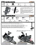
- Attach 3229 Body Post to 3308 Trans Brace using 3229 Screw.
- Slide 3201 Post Collar onto the Body Post and secure using 3229 Set Screw.

- Mount the 1202 Trans Spacer to the Chassis using the 5262 Screw where shown.
- Secure the Trans to the Chassis using (2) 5264 Screws thru the 1202 Trans Spacer as shown.
- Attach the 3308 Trans Brace to the Trans and Rear Bulkhead using 5253 Screws.
- Mount the Trans Brace to the Trans and Rear Bulkhead using 5253 Screws.
- NOTE: Align the dogbone shafts into the outdrives of Trans as you mount the trans!

3229                 Qty 1
8-32 x 1/2 FH Screw

1:1

Bag G

Bag G

Bag G

Bag G

Bag G

Bag H

Bag H

Bag H

Bag H

Bag H

5262                Qty 1
4-40 x 1/4 FH Screw

3229

3229

5264

5253

1202

5262

- NOTE: Align the dogbone shafts into the outdrives
of Trans as you mount the trans!

3308

3308

Summary of Contents for Outlaw 0720

Page 1: ......

Page 2: ...set up Custom Works has found in testing on different types of tracks however there are various other suspension configurations available to you that you may find more suitable for your local track F...

Page 3: ...mponents Steering Components Steering Components Steering Components Steering Components Parts for Step 1 Parts for Step 2 3203 Qty 2 Left Shown 25 Deg Castor Block 7200 Qty 2 Front Axle 7209 Qty 2 Sp...

Page 4: ...r Suspension Rear Suspension Rear Suspension Rear Suspension Rear Suspension 4234 Qty 2 Rear Inner Susp Pin 3254 Qty 2 Long Rear Susp Arm 5253 Qty 2 4 40 x 3 8 BH Screw 1 1 3305 Qty 1 Tail Tank Tray P...

Page 5: ...e Bearing Carrier Retain the Susp Pin using 5230 E Clips Apply grease to the areas shown Apply thread lock Loctite to the set screw Align the holes as shown so that the 7211 CVD Pin can pass thru the...

Page 6: ...n Casing 1230 Qty 2 3 8 x 5 8 Bearing 1226 Qty 4 3 16 x 3 8 Bearing 1 1 Parts for Step 1 Step 2 4368 Qty 1 Top Drive Shaft 1 1 4352 Qty 1 Transmission Halfs 1 1 4355 Qty1 Idler Pin Press the 2 1230 Be...

Page 7: ...3308 Qty 1 Transmission Brace 1 1 3229 Qty1 Short Body Post 3229 Qty 1 Post Collar 1202 Qty 1 Trans Spacer 5264 Qty 2 4 40 x 1 2 FH Screw 5253 Qty 4 4 40 x 3 8 FH Screw Attach 3229 Body Post to 3308...

Page 8: ...teps 5 8 Filling Shocks Steps 1 4 Setting Shock Rebound Steps 5 8 Filling Shocks Steps 1 4 Setting Shock Rebound Steps 5 8 4 Thread the Eyelet Cap assembly onto the Shock Body until it is hand tight O...

Page 9: ...5263 Qty 5 4 40 x 3 8 FH Screw 8122 Qty 2 Ball Stud 5240 Qty2 Servo Mount 3209 Qty1 Antenna Mount Bag I Bag I Bag I Bag I Bag I Bag J Bag J Bag J Bag J Bag J 2004 Qty 2 Strap Mount 3009 Qty 1 Strap Bu...

Page 10: ...6 4 40 x 1 2 BH Screw 1 1 5255 Qty 4 4 40 x 5 8 BH Screw 3232 Qty 1 Nerf Bar L R 3232 Qty 1 Nerf Support L R 5280 Qty 2 Hole Head Screw SHORT 5279 Qty 2 Hole Head Screw LONG 5278 Qty 2 4 40 x 1 SH Sc...

Page 11: ...1 Wing Slide Bushing to the Cage using 5254 Screws thru the Bushing and Cage and into the 3235 Upper Cage Brace Use the 2 Long 5279 Hole Head Screws mount the 3235 Upper Cage Braces onto the top of th...

Page 12: ...o fit the Body Template provided Use the Body Template ONLY to cut the front edge of the Right Body Panel Follow the molded lines on the 9029 Eagle Hood and 9026 Tail Tank Addtional trimming may be re...

Page 13: ...STEP 3 Place the wheel inside of the tire and work both beads of the tire into the channels on the outside edge of the wheel Peel back a portion of the tire from the wheel and apply an even bead of ti...

Page 14: ...Tire Raise Front Ride Height Lower Rear Ride Height Thread Shock Collar DOWN on Right Front Thread Shock Collar UP on Right Rear Increase Rear Toe Increase Castor Decrease Rear Toe Stagger or Decreas...

Page 15: ...increase front traction especially entering the turn Generally its safe to start the car with the ride heights even Rear Toe In Rear Toe In Rear Toe In Rear Toe In Rear Toe In Front edge of car tires...

Page 16: ...erefore more suitable for short tracks where you are constantly turning Wheelbase Rear End Wheelbase Rear End Wheelbase Rear End Wheelbase Rear End Wheelbase Rear End This adjustment uses the plastic...

Reviews: