I.B. 17555
Page 36
Effective 03/97
5-5.2 INITIAL POWER APPLICATION
a) Apply control power to the Digitrip 3000 Protective
Relay. Refer to Paragraph 3-2 entitled “Power-up
And Self Testing.”
b) Insure that the Operational LED on the front of the
relay is blinking green.
5-6 MISCELLANEOUS TESTING
DO NOT PERFORM DIELECTRIC TESTING
BETWEEN THE DIGITRIP’S METAL BACKPLATE OR
THE EARTH GROUND TERMINAL (TB1-4) AND
EITHER OF THE CONTROL VOLTAGE INPUT TERMI-
NALS (TB1-5,TB1-6) AND AUXILIARY “52B” INPUT
TERMINALS (TB1-9, TB1-10). BOTH OF THESE
SETS OF TERMINALS HAVE SURGE PROTECTION
MOVS INSTALLED TO EARTH GROUND AND
COULD BE ADVERSELY AFFECTED BY SUCH
TESTING.
Dielectric Notes:
1. The current transformer input terminals labeled
(A1,A2), (B1,B2), (C1,C2) and (G1,G2) are 5 ampere
type current, transformer inputs. These inputs have a
3000 volt ac breakdown rating for 1 minute between
phases.
2. The relay output contacts COMMUNICATIONS
CLOSE, TRIP INST AND TRIP OC/COMMUNICA-
TIONS have a 2000 volt ac breakdown rating for 1
minute between open contacts. The relays trip alarm
and protection off alarm have a 1000 volt ac break-
down rating.
3. All other terminals have a 1500 volt ac breakdown
voltage for 1 minute to earth ground except for the
above CAUTION restraint.
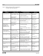
Table 5.1 Digitrip 3000 Dip Switch Settings
➀
Switch
Function
Switch Positions
ON
OFF
S1
IMPACC Buffers
Digitrip 3000
Digitrip MV
S2
Program with Breaker
Open or Closed
Open Only
S3
Trip Relay Configuration
Phase/Ground
OC/Inst
S4
Remote Open/Close
Enable
Disable
S5
Reserved
XXX
XXX
S6
Reserved
XXX
XXX
S7
Reserved
XXX
XXX
S8
Download Setpoints
Enable
Disable
S9
Auto-Reset
Auto
Manual
S10
Reserved
XXX
XXX
➀
For additional DIP Switch information, refer to Paragraph 2-2.2.
!
CAUTION


