I.B. 17555
Page 37
Effective 03/97
SECTION 6: MAINTENANCE AND
STORAGE
6-1 GENERAL
The Digitrip 3000 Protective Relay is designed to be a
self contained and maintenance free unit. The printed
circuit boards are calibrated and conformally coated at
the factory. They are intended for service by factory
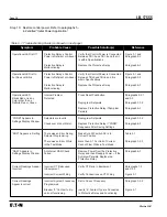
trained personnel only. The Troubleshooting Guide
(Table 6-1) is intended for service personnel to identify
whether a problem being observed is external or internal
to the unit. If a problem is identified to be internal, the
unit should be returned to the factory for repair or
replacement as described in Paragraph 6-3.
6-1.1 STORAGE
The Digitrip 3000 Protective Relay should be stored in
an environment that does not exceed the specified stor-
age temperature range of -40°C to +70°C. The environ-
ment should also be free of excess humidity. There are
no aluminum electrolytic capacitors used in the relay,
therefore it is not a requirement to power the unit occa-
sionally. If possible, the relay should be stored in its
original packing material and container.
6-2 TROUBLESHOOTING GUIDE (TABLE 6-1)
ALL MAINTENANCE PROCEDURES MUST BE PER-
FORMED ONLY BY QUALIFIED PERSONNEL WHO
ARE FAMILIAR WITH THE DIGITRIP 3000 PROTEC-
TIVE RELAY, THE ASSOCIATED BREAKER AND
CURRENT LINES BEING MONITORED. FAILURE TO
OBSERVE THIS WARNING COULD RESULT IN SERI-
OUS INJURY, DEATH AND/OR EQUIPMENT DAM-
AGE.
TROUBLESHOOTING PROCEDURES MAY INVOLVE
WORKING IN EQUIPMENT AREAS WITH EXPOSED
LIVE PARTS WHERE THE HAZARD OF A FATAL
ELECTRIC SHOCK IS PRESENT. PERSONNEL
MUST EXERCISE EXTREME CAUTION TO AVOID
INJURY OR EVEN DEATH.
ALWAYS DISCONNECT AND LOCK OUT THE CUR-
RENT SOURCE AND CONTROL POWER SUPPLY
BEFORE TOUCHING THE COMPONENTS ON THE
REAR OF THE DIGITRIP 3000 PROTECTIVE RELAY.
6-3 REPLACEMENT
Follow these procedural steps to replace the Digitrip
3000 Protective Relay.
Step 1:
Turn off control power at the main disconnect
or isolation switch of the control power supply.
If the switch is not located in view from the
relay, lock it out to guard against other per-
sonnel accidentally turning it on.
Step 2:
Verify that all “foreign” power sources wired to
the relay are deenergized. These may also be
present on the alarm terminal block. Current
transformer inputs must be temporarily short-
ed at a point prior to the relay’s terminals
before attempting to open these terminals on
the Digitrip 3000.
Step 3:
Before disconnecting any wires from the unit,
make sure they are individually identified to
assure that reconnection can be correctly per-
formed. Make a sketch to help with the task of
terminal and wire identification.
Step 4:
Remove wires by loosening or removing the
screw terminal where there is a wire connec-
tion.
Step 5:
Remove the 6 mounting screws holding the
unit against the door or panel. These are
accessed from the rear of the relay.
SUPPORT THE PROTECTIVE RELAY FROM THE
FRONT SIDE WHEN THE SCREWS ARE LOOSENED
OR REMOVED. WITHOUT SUCH SUPPORT, THE
PROTECTIVE RELAY COULD FALL OR THE PANEL
COULD BE DAMAGED.
Step 6:
Carefully lay the screws aside for later use.
Step 7:
Mount the replacement unit. Read paragraph
5-2.2 before attempting this.
Step 8:
Reverse the procedure outlined in Steps 4
and 5.
Step 9:
Using the sketch mentioned in Step 3, replace
each wire at the correct terminal. Be sure that
each is firmly tightened. Remove temporary
shorts on incoming current transformers.
!
WARNING
!
CAUTION


