I.B. 29C891B
Page 38
Effective 11/98
Notice:
Basic protection functions are not affected dur-
ing the performance of testing procedures.
Before starting a test sequence, check to be sure that the
Operational Status
LED on the face of the OPTIM Trip
Unit is blinking at approximately a 1 second on-off duty
cycle, indicating power is being applied to the trip unit and
it is functioning normally (Figures
2-4
and
2-10
). In the
event that the LED is not blinking at this rate, check to be
sure that control power is available or the battery in the
OPTIMizer Hand Held Programmer is good.
When performing tests, keep in mind that different com-
binations of protection features can contribute to the
results of the testing, and be the cause of unexpected
tripping actions.
Long delay thermal memory or
ground fault memory, for example, could result in an
unexpected tripping action.
Paragraphs 3-2.4 and 3-
2.7 should be reviewed if there are any questions.
Keep in mind that the
Trip Reset
pushbutton located on
the front of the trip unit will have to be pushed to reset
trip unit conditions after a test is completed that causes
the circuit breaker to trip and LED indicators to be lit
(Figures
2-4
and
2-10
).
3-5.4 PERFORMANCE TESTING FOR GROUND
FAULT TRIP UNITS
Code Requirements
The National Electrical Code under Article 230-95-C
requires that any ground fault protection system be per-
formance tested when first installed. The test shall be
conducted in accordance with approved instructions
provided with the equipment. A written record of this test
shall be made and available to the authority having
inspection jurisdiction.
Standards Requirements
As a follow-up to the basic performance requirements
stipulated by the N.E.C. in Section 6.2.1, UL Standards
No. 1053 requires that certain minimum instructions
must accompany each ground fault protection system.
The following article plus the test record form illustrated
in Figure
3-21
are intended to satisfy this requirement.
General Test Instructions
The interconnected system shall be evaluated in accor-
dance with the equipment assembler’s detailed instruc-
tions by qualified personnel.
The polarity of the neutral sensor connections, if used,
must agree with the equipment assembler’s detailed
instructions to avoid improper operations following
apparently correct simulated test operations. Where a
question exists, consult the specifying engineer and/or
equipment assembler.
The grounding point of the system shall be verified to
determine that ground paths do not exist that would
bypass the sensors. The use of high voltage testers and
resistance bridges may be used.
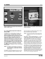
Figure 3-19 Auxiliary Power Module
Summary of Contents for Digitrip OPTIM 1050
Page 7: ......


