Page 12 of 44
Remote Control System
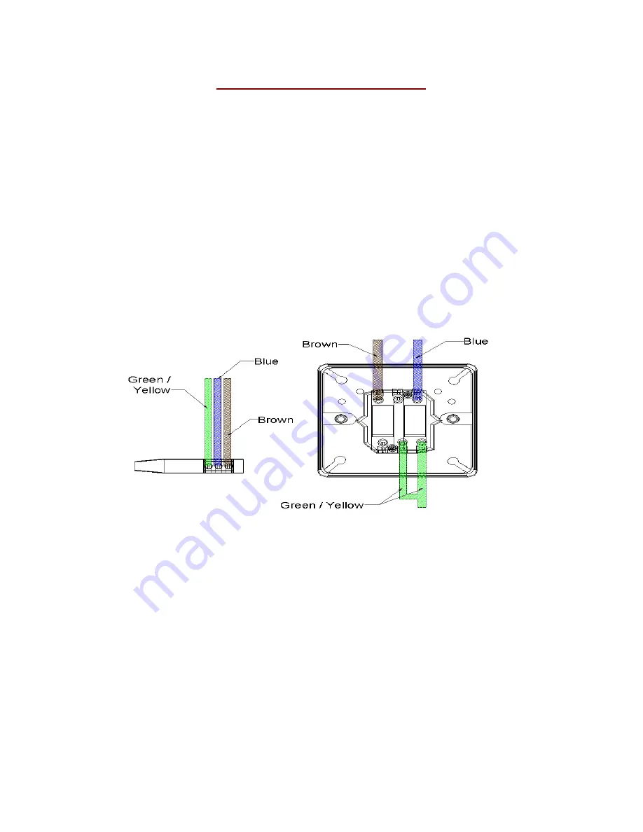
The remote system is supplied with both the hard-wired wall mounted switch
and infrared hand held system as standard. Both options allow full control of
the fire – ON, OFF, UP, DOWN. The wall mounted switch and cable carries low
voltage, (20v). The colour code used in the switch wiring diagrams must not be
confused with normal mains colour coding.
Use and install both systems. This gives increased reliability and is
recommended by CVO. The removal of the remote components can lead to
accidental damage of the remote system which will not be covered by the
warranty. The magic eye is situated on the fascia and great care must be taken
on plugging this into the control board. When running the cabling for the
hardwire great care must be taken to ensure that the switch is wired correctly
(see image below taking notice of the “top” of the switch which is where the
Blue/Brown are attached.
Summary of Contents for Fire River
Page 4: ...Page 4 of 44 ...
Page 8: ...Page 8 of 44 Component List Specification ...
Page 9: ...Page 9 of 44 ...
Page 11: ...Page 11 of 44 LPG Version Natural Gas Version ...
Page 19: ...Page 19 of 44 Magic Eye Position ...
Page 24: ...Page 24 of 44 The Remote Control Black Box Remote Valve NG Version LPG Version ...
Page 26: ...Page 26 of 44 SEAGAS PILOT ASSEMBLY ...
Page 27: ...Page 27 of 44 Remote Wiring Diagram With SIT Pilot ...
Page 28: ...Page 28 of 44 Remote Wiring Diagram with SEAGAS Pilot ...
Page 32: ...Page 32 of 44 ...
Page 33: ...Page 33 of 44 PIN NUMBER 0558CN1404 Rev 10 Fire River USER HANDBOOK ...
Page 39: ...Page 39 of 44 Infra Red Remote Replacing the Battery ...
Page 43: ...Page 43 of 44 ...


