28
place it where the monitoring computer is located. You may wish to place the COM1: Icon
with the PC or the Panel it is your choice as the cable connects the two devices.
13.
Now click on the
Select
button and select the imported image,
Westside Hotel - Bldg 1,
First Floor
.
14.
You can zoom into any area by left clicking and dragging your mouse to the opposite corner.
Right clicking and selecting
View All
resets the zoom level to the entire image.
15.
Right click on the image and select
Insert Device
, a popup window will list all of the devices
you have imported from the CP-3000DA that have not been placed. Select a device on the
list and drag it onto the background image and place it at the correct physical location that
matches the installation site. Repeat as necessary until you have placed all of the devices for
the area depicted in the background image.
16.
If you have multiple areas / floors, import an image for each area and place the devices for
each area. If you enroll a whole new floor of devices into the CP-3000DA panel, simply
create a new system summary file as detailed above and import it. Your placed devices will
not be moved.
17.
If you accidentally place a device on the wrong floor, right click on it and select
Delete
.
Select the proper floor and place it there. If you need to move a device on the floor to a new
location, right click on it and select
Edit
and then drag it to the new location with the mouse.
18.
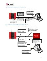
Connect the serial cables as indicated in the diagrams Figure 1 and Figure 2 at the end of the
document depending upon whether you do or do not have an External Dialer.
19.
If your COM Port is not COM1
, change the COM port on the Configuration Manager :
Setup -> System COM Ports
, Select COM1: and then change the COM
Port ID:
to match
your PC, i.e. COM3.
20.
If you are using a Serial to USB adapter, please note that the
System Monitor
program will
have to be restarted if you pull the USB cable out of the PC as the USB COM port
connection will be lost simply plugging the USB cable back in will not restore the connection
inside
System Monitor
. If only the DE9 connector is disconnected the COM port stays
active and merely needs to be reconnected. In both cases the System Watch program will
alert the user that the COM port has been lost.
21.
Now that you have connected the CP-3000DA panel to the CWSite PC you may need to
enable the serial data stream. IF an external Keltron Dialer is connected to the CP-3000DA
panel it may already be enabled. To enable the Serial Data stream on the CP-3000DA go to
Program -> CP-3000DA Setup -> Dialer Setup
and if the
Keltron SDACT Enabled:
is
not set to
On
, select it and change to
On
and press
Save
.
22.
Restart
System Monitor
and it will establish a connection with the COM port.
23.
Turn on
Display Event Data
,
Display Connect Status
and
Display Incoming Data
so that
you can monitor the data stream as you test your installation.
24.
Start
System Watch
by double clicking on it.
25.
Trigger troubles on the enrolled devices and
CWSite
will display the matching trouble on the
System
Watch
device log. Double click on the message and it will take you to the device
Summary of Contents for CP-3000A
Page 21: ...20...


