Leased Line Operation
V.34bis Series Standalone & Rackmount Modems
67
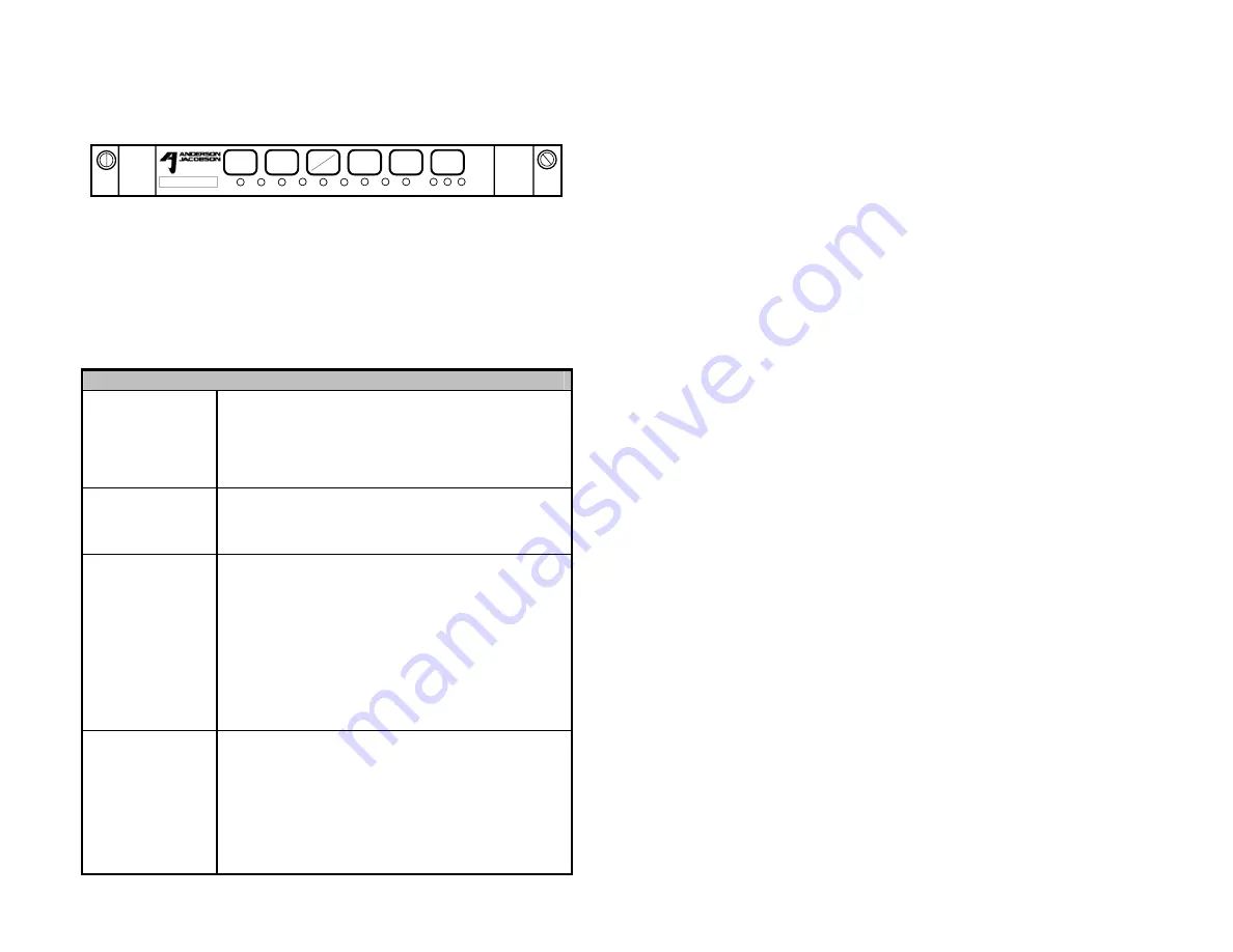
Rackmount Front Panel Operations
CTS
CD
DSR
DTR/
PWR
SQ
TD
RD
ERR
TST
HIGH MED LOW
DIAL
FBS
DISC
ANS
ORIG
RDL
LAL
Figure 4
The front panel of the AJ Rackmount has six touch switches and 12 LEDs.
The LEDs indicate th operating status of the modem and are described in
Table 4.2. The front
pictorial above. The
All switch actuation a
Note: T
S102 to a “1
.1: Rackmount Modem Front Panel
e
panel switches, the LEDs and their labels are shown
functions of the switches are given in Table 4.3 below.
re momentary unless otherwise noted.
he front panel may be disabled by setting Bit 2 of S-Register
".
Table 4.3 - Rackmount Front Panel Functions
LAL
Pressing this switch initiates the Local Analog
Loopback Test when off-line. Pressing this switch
initiates the Local Digital Loopback Test when on-line.
Pressing this switch a second time terminates the test.
These tests do not use the internal test generator and
comparator.
RDL
this switch initiates the Remote Digital
Pressing
Loopback Test when on-line. Pressing this switch a
second time terminates the test. This test does not
use the internal test generator and comparator.
ORIG/ANS
isplay.
When off-line, momentarily pressing this switch
causes the modem to go off-hook and operate in the
originate mode, and pressing the switch for more than
2 seconds causes the modem to operate in the
answer mode. If this switch is pressed when a ring
signal is being received, the modem will be forced off-
hook in the answer mode. If the modem is on-line and
this switch is pressed, the operating configuration will
be displayed by the appropriate LED. Pressing the
switch a second time will terminate the configuration
d
DISC
the telephone line in
dial up or leased line operation, and returns the
modem to the Command Mode. Holding this switch
for more than 4 seconds causes the modem to
disconnect and then perform a hardware reset (same
as the power reset). Immediately after the power-up
test and the three beeps, the appropriate LED will
indicate for 2 seconds the configuration that is loaded.
When on-line, momentarily pressing the switch causes
the modem to disconnect from
Summary of Contents for V.34bis series
Page 10: ...Introduction 6 V 34bis Series Standalone Rackmount Modems ...
Page 22: ...Installation 18 V 34bis Series Standalone Rackmount Modems ...
Page 40: ...Modes and Configurations 36 V 34bis Series Standalone Rackmount Modems ...
Page 65: ...Modes and Configurations V 34bis Series Standalone Rackmount Modems 61 ...
Page 118: ...AT and V 25bis Command Sets 114 V 34bis Series Standalone Rackmount Modems ...
Page 128: ...S Registers 124 V 34bis Series Standalone Rackmount Modems ...
Page 150: ...Index 146 V 34bis Series Standalone Rackmount Modems ...


