background image


Bypass Mode 

When no PV power  during On Grid operation, unit  off internal switch but keep bypass relay on to 
continuously supply loads power from Grid directly. 
 

Charger Mode 

If user doesn’t want On-Grid, bypass or Off-Grid operation, wants all PV power to charge battery. Either one 
of below ways can make unit stay in charger mode. 

-


Disconnect Grid O/P and Standalone, power on PV power. 

-


Press and hold button for 3s during operation (unit  would back to On-Grid operation after PV 
power off and on) if Grid is available. 

 
Sleeping Mode 

User can off unit by press and hold the button for 3s during unit operation. In this mode, unit off all LEDs to 
save energy but keep monitoring the internal system for quickly going back to normal operation. When PV 
power comes back, unit  will enter charger mode automatically.  When PV power is gone, unit  will enter 
shutdown mode. 

 
Shutdown Mode 

Unit automatically stop running during no PV power and low battery. In shutdown mode the units take no 
power from panel and battery. If Grid is available, the inner charger would continuously charge battery but 
without any LED indicator. If user wants to check the capacity of battery in this mode, can press the button 
and see the battery LED color. 

 
De-rating mode 

When temperature high or PV voltage >38Vdc, the unit will de-rate its output power.   
 

6.3 Charge Current Setting 


Risk of damage to the unit   
Adjust the charge current according the total Ah value of battery and don’t 
more than 0.3C (ex. Set 2Amax for 9Ah, 6Amax for 20Ah). Larger charge 
current to lower capacity battery can reduce the life of battery. 

User can set the charge current as 1/2/3/5/7/9A (default is 1A).   
Note: The charger power comes from PV. Larger charge current would reduce the feeding power to Grid 
and/or loads. 
 
Procedure for changing charge current, 
Press and hold the button. 

 3s later, unit shutdown and all LEDs are red 

 Another 3s later, all LEDs are 

green 

 Another 3s later, BAT LED is blinking with green and the other LEDs are orange, release the button 

immediately. 

 PV LED on green and red alternately, means unit stay in setting mode. 

Note:  It is not able to enter setting mode if user don’t release the button within 4s when all LEDs are 
orange, must release the button and redo the procedures. 
Now, user can change the charge current by pressing button (refer to Table 6-1 for the setting). 


NOTICE

!

User Manual                                       

14                                Hybrid CPSHB300ETR-IN   

Summary of Contents for CPSHB300ETR-IN

Page 1: ...User s Manual CPSHB300ETR IN Cyber Power Systems Inc www cyberpower com ...

Page 2: ......

Page 3: ...he Unit 4 3 Product Description 5 3 1 CPS Solar Hybrid Power Generating System Overview 5 3 2 Size and Weight 5 3 3 Transportation 6 3 4 Storage of Unit 6 3 5 The Advantage of CPS Solar Hybrid Power Generating Systems 6 4 Unpacking 7 5 Installation 8 5 1 Safety Instruction 8 5 2 Selecting the Installation Location 8 5 3 Electrical Connections 9 5 3 1 Safety 9 5 3 2 Wiring PV Input 10 5 3 3 Wiring ...

Page 4: ...id Operation 19 7 2 USB Charger Only 19 7 3 Start up the Unit for Off Grid Operation 19 7 4 Shut down the Unit 20 8 Maintenance 21 8 1 Replace the Internal Batteries 21 8 2 Replace the Fuse 22 9 Decommissioning 23 9 1 Dismantling the Unit 23 9 2 Packing the Unit 23 9 3 Disposing of the Unit 23 10 Specification 24 10 1 Specification of CPSHB300ETR IN 24 10 2 Torque Values 25 11 Contacts 26 ...

Page 5: ... prohibited installation positions 9 Fig 5 2 Clearance space for installation 9 Fig 5 3 Grid output and standalone output connections 10 Fig 5 4 Connect PV connectors to unit 11 Fig 5 5 The location of extended battery connector 12 Fig 7 1 Power flow of On Grid operation 19 Fig 7 2 Power flow of Off Grid operation 20 Fig 8 1 Procedure of replacing batteries 21 Fig 8 2 Grid O P fuse replacement 22 ...

Page 6: ... of Figures Table 6 1 Charge current setting 15 Table 6 2 LEDs indicators for On Grid operation 16 Table 6 3 LEDs indicators for Off Grid operation 17 Table 10 1 Specification 24 Table 10 2 Torque values 25 ...

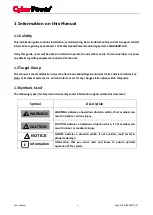
Page 7: ...ectricity and electrical devices Note CyberPower Systems Inc will not inform users for any changes taken place within this guide 1 3 Symbols Used The following types of safety instructions and general information appear within this document Symbol Description WARNING indicates a hazardous situation which if not avoided can result in death or serious injury CAUTION indicates a hazardous situation w...

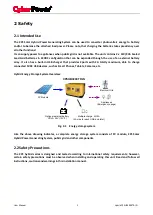
Page 8: ...VDC USB devices such as Smart Phones Tablets Cameras etc Hybrid Energy Storage System Overview PV Module Electrical Grid Appliances Emergency usage Multiple charge 5V 2A 2A max for each USB and total CPSHB300ETR IN Optional external battery VRLA 24V 12V 2 Fig 2 1 Energy storage system Like the above drawing indicates a complete energy storage system consists of PV module CPS Solar Hybrid Power Gen...

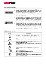
Page 9: ...ll electrical connections e g conductor termination fuses PE connection etc in accordance with prevailing regulations When working with the unit powered on adhere to all prevailing safety regulations to minimize risk of accidents The unit may only be operated with PV generators modules and cabling with protective insulation Do not connect any source of energy other than PV modules to the CPS hybri...

Page 10: ...d secure during operation Although designed to meet all safety requirements some parts and surfaces of Unit are still hot during operation To reduce the risk of injury do not touch the surfaces while Unit is operating Incorrect sizing of the PV plant may result in voltages being present which could destroy the unit Anytime the unit has been disconnected from the power network use extreme caution a...

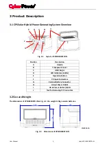
Page 11: ... USB Charger D LED Indicators 4 LEDs E Operation Button F PV Input Connectors G External Battery Connector H AC out Power Outlet I AC in Power Outlet GRID J Tool for Removing PV Connectors 3 2 Size and Weight The dimensions of CPSHB300ETR IN as Fig 3 2 the weight is 9kg includes batteries Unit mm Fig 3 2 Dimensions of CPSHB300ETR IN 292 186 202 User Manual 5 Hybrid CPSHB300ETR IN ...

Page 12: ...your warehouse you should choose an appropriate location to store the unit The unit must be stored in original package and desiccant must be left in the package For the life and capacity of battery the storage temperature should be always between 10 and 40 And the storage relative humidity should be always between 0 and 95 After long term storage local installer or service department of CyberPower...

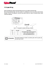
Page 13: ...mages or parts missing please contact your dealer Complete delivery should contain the following A B C Fig 4 1 Components included in the scope of deliver Item Quantity Description A 1 Solar Hybrid Power Generating System B 1 Power cord for AC connection C 1 User manual Warranty Card Even though packaging is made to be durable please treat it gently and avoid tossing it around i Information User M...

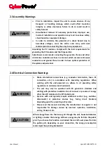
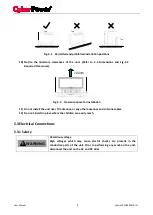
Page 14: ...ntil at least 2 minutes after disconnecting all power sources Although designed to meet all safety requirements some parts and surfaces of unit are still hot during operation To reduce the risk of injury do not touch the surfaces of unit during operation 5 2 Selecting the Installation Location The points below help you select a suitable installation location thus avoiding any potential damages to ...

Page 15: ...the unit near TV antennas or any other antennas and antenna cables 12 Don not install in place where the children can easily reach 5 3 Electrical Connections 5 3 1 Safety Hazardous voltage High voltages which may cause electric shocks are present in the conductive parts of the unit Prior to performing any work on the unit disconnect the unit on the AC and DC sides Top Top Top WARNING User Manual 9...

Page 16: ...r exposed terminals Cover the panel with an opaque material before making PV input connection To reduce the risk of electric shock avoid touching the live components and treat the terminals carefully NEVER connect or disconnect the DC connectors under load Risk of damage to the unit If the voltage of the PV modules exceeds the maximum input voltage of the unit it can be destroyed by the overvoltag...

Page 17: ...rminals carefully NEVER connect or disconnect the connectors under load Risk of damage to the unit If the voltage of the battery exceeds the maximum input voltage of the unit it can be destroyed by the overvoltage This will void all warranty claims If the polarity of battery is reversed connect it can damage the unit fuse and unit can t operate anymore Before connecting make sure the polarity is c...

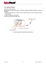
Page 18: ...pen the transparent cover and plug in the AC power cord the other end of power cord plug to electrical socket 2 Plug in the load power cord if needed Note Please use the accessorial power cord Different area has different plug type or or To loads appliances Electrical socket Fig 5 5 Grid output and standalone output connections User Manual 12 Hybrid CPSHB300ETR IN ...

Page 19: ...d reduce the input power to make the net power to Grid as zero 6 2 Operation Modes Self consumption On Grid Mode In this mode the unit convers PV power to charging battery and or to balance the load power consumption Whenever the DC voltage is lower than 25Vdc the unit will work in waiting state and attempt to connect the grid by 5mins for 25Vdc and 30s for 16Vdc In waiting state the unit continuo...

Page 20: ...ut any LED indicator If user wants to check the capacity of battery in this mode can press the button and see the battery LED color De rating mode When temperature high or PV voltage 38Vdc the unit will de rate its output power 6 3 Charge Current Setting Risk of damage to the unit Adjust the charge current according the total Ah value of battery and don t more than 0 3C ex Set 2Amax for 9Ah 6Amax ...

Page 21: ...Orange 9A Procedure for confirming charge current setting and exiting setting mode When the charge current setting is changed to what user wants Press and hold the button 3s later unit confirms the setting and exit setting mode jump to Sleep mode and all LEDs off When all LEDs are Green release the button immediately Unit goes back to normal operation User Manual 15 Hybrid CPSHB300ETR IN ...

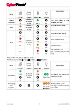
Page 22: ...repare to On Grid operation Discharging Inner Capacitor Orange with fast flashing Before shutdown unit discharges inner Bus capacitor around 10s Normally Operating Green Green Green Off Operating normally with battery capacity 75 Green with slowly flashing Operating normally with battery capacity between 50 and 75 and under charging Orange with slowly flashing Operating normally with battery capac...

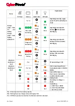
Page 23: ...tion fault Any Orange Off Grid is abnormal Any Red Off Internal fault occurs ex CT test fail relay test fail etc Table 6 3 LEDs indicators for Off Grid operation Flash frequency on off 2s 1s 0 5s 0 5s 0 2s 0 2s Status PV Panel Battery AC On Grid Off Grid Explanation Countdown Green Off Depend on the status of battery Orange Off Green Flash Countdown and self test for Off Grid operation Discharging...

Page 24: ...ault Orange Red with fast flashing C Orange Off Green Operating normally with battery 25 and under discharging Orange Green Off A C Orange Off C Orange Off Off PV panel voltage 50V A B Orange Unit is operating with over load output power 240W or 300VA A Red Unit is Off A Fault or Over Load or Low Battery condition has Occurred Red Off Battery Fault No battery or voltage is 31Vdc Red Red Low batter...

Page 25: ...ly With PV power When PV voltage has sufficient power USB charger will automatically operate Without PV power 1 Make sure the unit is staying in shutdown mode 2 Disconnect Off Grid plug 3 Press and hold the button until all LEDs are green it takes around 1 2s release the button immediately when the LEDs are green 4 USB charger starts to operate 7 3 Start up the Unit for Off Grid Operation With PV ...

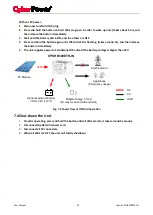
Page 26: ...supplies power to Standalone O P outlet if the battery voltage is higher than 22V PV Module Electrical Grid Appliances Emergency usage Multiple charge 5V 2A 2A max for each USB and total CPSHB300ETR IN Optional external battery VRLA 24V 12V 2 DC AC USB X Fig 7 2 Power flow of Off Grid operation 7 4 Shut down the Unit 1 If unit is operating press and hold the button until all LEDs are red it takes ...

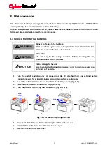
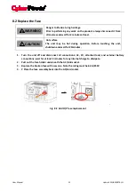
Page 27: ...and wait for 20minutes Risk of damage to the unit Note the polarity of connection reverse connection can cause fuse open and unit can t operate 1 Turn the unit off and disconnect all connections AC PV attached load and external battery connections wait for at least 2minutes for any internal charge to dissipate 2 Invert the unit and remove the 4 screws from the battery s cover Fig 8 1a 3 Slide the ...

Page 28: ...ait for 20minutes 1 Turn the unit off and disconnect all connections AC PV attached load and external battery connections wait for at least 2 minutes for any internal charge to dissipate 2 Pull out the fuse holder underneath the AC Grid socket 3 Replace the broken fuse with new one Note the rating must be 6 3A 250V 4 P Place the fuse assembly back into the AC Grid socket Fig 8 2 Grid O P fuse repl...

Page 29: ...ompletely and made to support both the weight and the size of the unit 9 3 Disposing of the Unit Do not dispose of faulty units or accessories together with household waste Please accordance with the disposal regulations for electronic waste which apply at the installation site at that time Ensure that the old unit and where applicable any accessories are disposed of in a proper manner Danger of b...

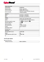
Page 30: ... voltage 24Vdc 12Vdc 2 Nominal Capacity 9Ah Discharge current Max 14A Charge current Settable max 1 2 3 5 7 9A from PV Max 0 5A from AC Shutdown voltage 20V for 100W 21V for 30 100W 22V for 30W Measurements deviation Voltage 2 Current 2 Power 3 USB Charger Nominal charge power 10W Nominal voltage 5Vdc Number of USB port 2 Max charge current 2A 2A per port total Grid AC Nominal voltage 230Vac singl...

Page 31: ...On Grid Off Grid LEDs Button One button for ON off and select functions Operation temperature range 10 50 de rating above 40 Storage temperature 20 40 Relative humidity 0 95 Operating elevation 0 2000m 0 6666ft Cooling Natural convection Overvoltage category II Protective class I Mechanical Dimension W H D mm 292 186 202 Weight 9kg Package dimension W H D mm 380 305 290 IP 21 10 2 Torque Values Ta...

Page 32: ...ease provide below information 1 Model Name 2 Serial Number 3 Detailed Error Description CyberPower Systems India Pvt Ltd NO 1107 11TH Floor Mittal Commercia Off Andheri Kurla Road Marol Andheri East Mumbai India 400059 T 022 28566100 F 022 28566110 E Sales cpsww co in www cyberpower com User Manual 26 Hybrid CPSHB300ETR IN ...

Page 33: ...Note ...

Page 34: ...Note ...

Page 35: ......

Page 36: ...www CyberPower com K01 0000634 00 ...

Reviews: