Table of Figures
Fig. 2-1 Energy storage system ....................................................................................................... 2
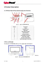
Fig. 3-1 Layout of CPSHB300ETR-IN ............................................................................................... 5
Fig. 3-2 Dimensions of CPSHB300ETR-IN ....................................................................................... 5
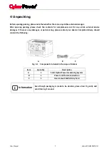
Fig. 4-1 Components included in the scope of deliver ................................................................... 7
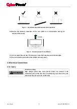
Fig. 5-1 Permitted and prohibited installation positions ............................................................... 9
Fig. 5-2 Clearance space for installation ........................................................................................ 9
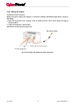
Fig. 5-3 Grid output and standalone output connections ............................................................ 10
Fig. 5-4 Connect PV connectors to unit ........................................................................................ 11
Fig. 5-5 The location of extended battery connector ................................................................... 12
Fig. 7-1 Power flow of On-Grid operation .................................................................................... 19
Fig. 7-2 Power flow of Off-Grid operation .................................................................................... 20
Fig. 8-1 Procedure of replacing batteries ..................................................................................... 21
Fig. 8-2 Grid O/P fuse replacement .............................................................................................. 22
Summary of Contents for CPSHB300ETR-IN
Page 1: ...User s Manual CPSHB300ETR IN Cyber Power Systems Inc www cyberpower com ...
Page 2: ......
Page 33: ...Note ...
Page 34: ...Note ...
Page 35: ......

