User Manual 26 / 61 CPS Mini Central series
1
Check the connection cables of the PV modules for correct polarity and make sure that the maximum
open circuit voltage of each string should never exceed 1000V.
2
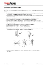
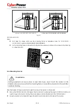
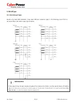
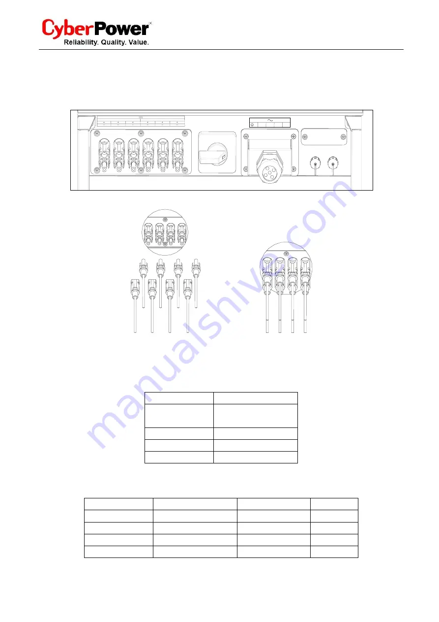
The diagram drawing of DC side is shown as below, notice that the connectors are in paired (male and
female connectors). The connectors for PV arrays and inverters are MC (multi-connector) connectors;
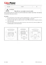
Fig.5.21
Fig.5.22
3
Check the assembled DC connectors for correct polarity and connect them to the inverter.
4
The maximum string currents are varying from different inverter types.
Type
Max. current
CPSPV7000ETL ~
CPSPV10000ETL
15A
CPSPV 12000ETL
17A
CPSPV 18000ETL
23A
CPSPV20000ETL
26A
5
In order to seal the inverter, all unneeded DC inputs must be closed with sealing plugs:
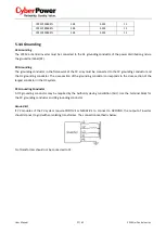
Cable requirements:
Model
Diameter(mm)
Area(mm²)
AWG
CPSPV7000ETL
2.05
3.332
12
CPSPV8000ETL
2.05
3.332
12
CPSPV9000ETL
2.05
3.332
12
CPSPV10000ETL
2.05
3.332
12
MPP Tracker A
MPP Tracker B
Do not disconnect under load!
DC switch
RS-232
RS-485
N
L1
L2
L3


