User Manual 30 / 61 CPS Mini Central series
6 Commissioning
6.1 Commission the Inverter
1)
Remove all covers from the PV array.
2)
Check the PV and AC voltage.
3)
Plug in the PV input.
4)
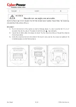
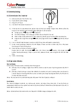
Turn the DC Disconnect to position "I".
Fig.5.26
5)
If the inverter is connected with PV panel arrays and the input voltage is higher than 300Vdc, while the
AC grid is not connected yet, LCD will display messages in order as below:
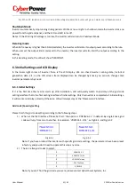
Company info Basic info State info
The LCD will display “ AC V outrange “at State info and the LED turns red.
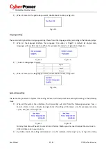
Please check all information on the LCD, operate by knocks you will see the different parameters.
Single knock to Light the backlight State info (single knock) Input info (single knock) Output
info
6)
Turn on the AC breaker between inverter and grid, the system will operate automatically.
7)
Under normal operating conditions, the LCD displays ‘Power: xx.xx Kw’ at State info, this is the power
feed into grid. The LED turns green.
8)
Check the time and date of inverter as follow:
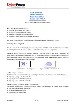
Single knock to Light the backlight State info (Thrice knock) Inverter info (single knock)
System Time(double knock), if they are not correct, please set them, refer to Fig
6.3.15 or 6.4.3 text
line.
9)
Finish commissioning.
6.2 Operation Modes
Normal Mode
In this mode, the inverter works normally and LED turns green.
Whenever the DC voltage is higher than 350Vdc, inverter converts power to grid as generated by the PV
panels;
Whenever the DC voltage is lower than 300Vdc, the inverter will work in waiting state and attempt to
connect the grid. In waiting state the inverter consumes just enough power generated by the PV panel to
monitor the internal system.
Notes: The inverter starts up automatically when DC power from the PV panel is sufficient.
Fault Mode
The internal intelligent controller can continuously monitor and adjust the system state. If inverter finds any
unexpected conditions such as system fault and inverter fault, the fault information will be displayed on the LCD. In
fault mode the LED turns red.
Notes: a) Detailed fault information refers to Chapter 9.1 ERROR messages displayed on LCD.

