User Manual 34 / 61 CPS Mini Central series
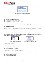
Fig6.3.6 Serial number, model name and version
Here is explanation of items on Fig6.3.6:
First line: Serial number of this inverter.
Second line: model name of this inverter.
Main Ver: firmware version of control board.
Comm Ver: firmware version of communication board.
After displaying information of the third interface for 3 seconds, the background light will turn off.
LCD Display when backlight off
After the power on information is displayed automatically and the backlight turns off, the LCD display will switch to
the following Interface 1. There are 4 interfaces, which can be displayed in turn by single knock.
Interface 1:
Running state. The first line displays inverter’s state description, for example, in faulty state it will
display ERROR and followed with faulty codes, which is convenient to compare with error code list in manual. The
second line displays inverter’s states name; and the third line displays energy generated today, and the fourth line
displays the total energy generated since installation.
Fig6.3.7 Interface 1: Running state Fig6.3.8 Interface 2: Input information
Interface 2:
Input information.
This interface displays parameters of PV input, including input voltage, current, and power of each MPP tracker.
V-pv: input voltage of MPPT1 and MPPT2
I-pv: input current of MPPT1 and MPPT2
P-pv: input power of MPPT1 and MPPT2
Interface 3:
Output information. See Fig6.3.9 for reference.
This interface displays output information of inverter, including output voltage of each phase, output current of
each phase, and output power of each phase.
V: output voltage of each phase
I: output current of each phase
State: Fault
ERROR 101
E_day: 00.0
E_All: 596


