19
HSTP3T 10-40 KE/KEBC/KEBCWOB User Manual
Chapter 2 Installation Instruction
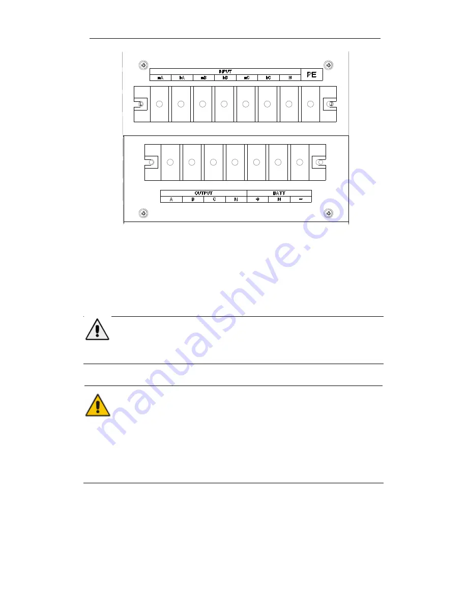
Fig.2-13 Connections terminals for 40kVA
3. Connect the protective earth wire to protective earth terminal (PE).
4. Connect the AC input supply cables to the Input terminal and AC output supply cables to
the Output terminal.
5. Connect the Battery cables to the Battery terminal.
6. Check to make sure there is no mistake and re-install all the protective covers.
Note: mA, mB, mC standard for Main input phase A,B and C; bA, bB, bC standard for
Bypass Input phase A,B and C.
Attention
The operations described in this section must be performed by authorized electricians or
qualified technical personnel. If you have any difficulties, contact the manufacturer or agency.
Warning
Tighten the connections terminals to enough torque moment, refer to Table 2.3, and
please ensure correct phase rotation.
The grounding cable and neutral cable must be connected in accordance with local and
national codes.
When the cable holes does not goes through by cables, it should be filled by the hole
stopper
2.7 Control and Communication Cables
The front panel of the bypass module provides dry contact interface (J2-J11) and
communication interface (RS232
,
RS485,SNMP ,Intelligent card interface and USB port)
,
as
it is shown in Fig.2-14.
Summary of Contents for HSTP3T10KE
Page 2: ...Ver 1 0 3 ...


