background image

Copyright ©  2012 Cyber


Power Systems, Inc.


BASIC OPERATION


6


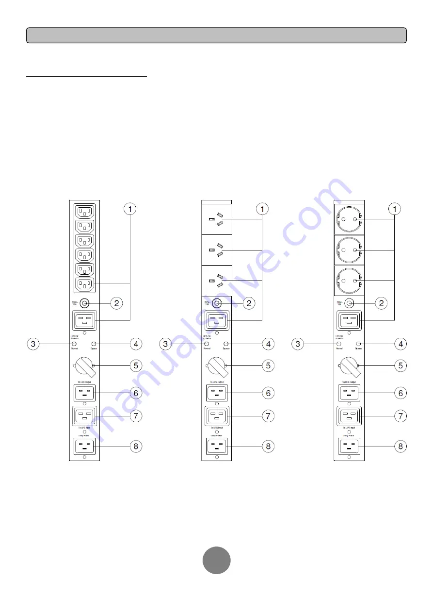
MBP FRONT PANEL DESCRIPTION


1. AC Output Outlets
Provide output power to the connected equipment. The supplied power
source  can  be  selected  by  manual  bypass  switch  to  ensure  nonstop
operation during maintenance or UPS replacement.

2. Output Circuit Breaker
Provide output overload and fault protection.

3. “Normal” LED Indicator
Indicate that the connected equipment is supplied by UPS output.

4. “Bypass” LED Indicator
Indicate that the connected equipment is supplied directly by utility power.

5. Manual Bypass Switch
Provide  UPS  output  to  connected  equipment  when  turned  to  “Normal”,
provide utility power to connected equipment when turned to “Bypass”.

6. “To UPS Output” Inlet
Connect the AC Power cord to UPS Output.

7. “To UPS Input” Outlet
Connect the AC Power cord to UPS Input.

8. “Utility Power” Inlet
Connect the AC Power cord to a properly wired and grounded outlet.

    MBP20HVIEC6 

MBP20HVAU3 

MBP20HVDE3


Summary of Contents for MBP20HVIEC6

Page 1: ...User s Manual MBP20HVAU3 MBP20HVDE3 MBP20HVIEC6 Cyber Power Systems Inc www cyberpower com K01 0000262 02 ...

Page 2: ...nel may carry out installations CAUTION Do not unplug the unit from AC Power during operation as this will invalidate the protective ground insulation CAUTION To avoid electric shock turn off and unplug the unit before installing the input output power cord with a ground wire Connect the ground wire prior to connecting the line wires CAUTION Do not use an improper size power cord as it may cause d...

Page 3: ...G 2 IEC AU or DE MBP Maintenance Bypass PDU User s manual Register card Rackmount brackets 2 Power Cord Retention Clips 4 C20 C19 Power cords 2 C20 C13 Power cord 1 C14 C19 Power cord 1 Flat head screws M4X8L 4 Pan head screws M5X12L 4 Cable Ties 4 ...

Page 4: ...ow for the respective mounting methods Step 1 Brackets installation Attach the two brackets to the MBP using the provided screws M4X8L 4pcs Step 2 MBP Installation Secure the MBP with the provided screws M5X12L 2pcs MBP mounted horizontally in a rackmount MBP mounted vertically in a rackmount Wall mounted MBP mounted with UPS in rackmount mode MBP mounted with UPS in tower mode 1 2 1 2 1 2 2 1 1 2...

Page 5: ...UTPUT 4 INPUT OUTPUT CONFIGURATION Connect the input output as shown in the following diagram 1K 1 5K configuration 2K configuration 3K configuration C14 C19 Power cord C13 C20 Power cord C14 C19 Power cord C13 C20 Power cord C19 C20 Power cord C20 C19 Power cord ...

Page 6: ... inserted Step 2 Retention Clip Installation Place a Retention Clip on the power cord Insert the power cord to the MBP Align and Insert the Cable Tie into the Retention Clip Step 3 Fasten Retention Clip Push the Retention Clip until it touches the plug and fasten the Retention Clip REMOVING THE RETENTION CLIP Step 1 Loosen Retention Clip Loosen the Retention Clip by pushing it to the right Step 2 ...

Page 7: ...ndicator Indicate that the connected equipment is supplied by UPS output 4 Bypass LED Indicator Indicate that the connected equipment is supplied directly by utility power 5 Manual Bypass Switch Provide UPS output to connected equipment when turned to Normal provide utility power to connected equipment when turned to Bypass 6 To UPS Output Inlet Connect the AC Power cord to UPS Output 7 To UPS Inp...

Page 8: ...ent is supplied by UPS output when the Manual Bypass Switch is turned to Normal The connected equipment is supplied by utility power when the Manual Bypass Switch is turned to Bypass Cyber Power Systems Inc www cyberpower com Entire contents copyright 2012 Cyber Power Systems Inc All rights reserved Reproduction in whole or in part without permission is prohibited PowerPanel Business Edition and P...

Reviews: