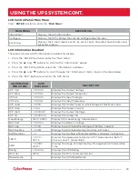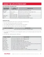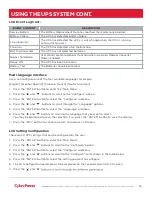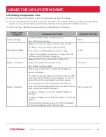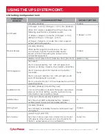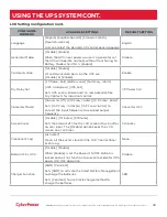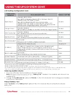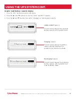
įĂĀĂĀƫ5!.ƫ+3!.ƫ5/0!)/ƫĨĩČƫ *ċƫ((ƫ.%#$0/ƫ.!/!.2! ċƫ((ƫ+0$!.ƫ0. !).'/ƫ.!ƫ0$!ƫ,.+,!.05ƫ+"ƫ0$!%.ƫ.!/,!0%2!ƫ+3*!./ċƫ
15
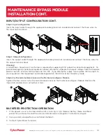
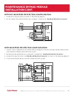
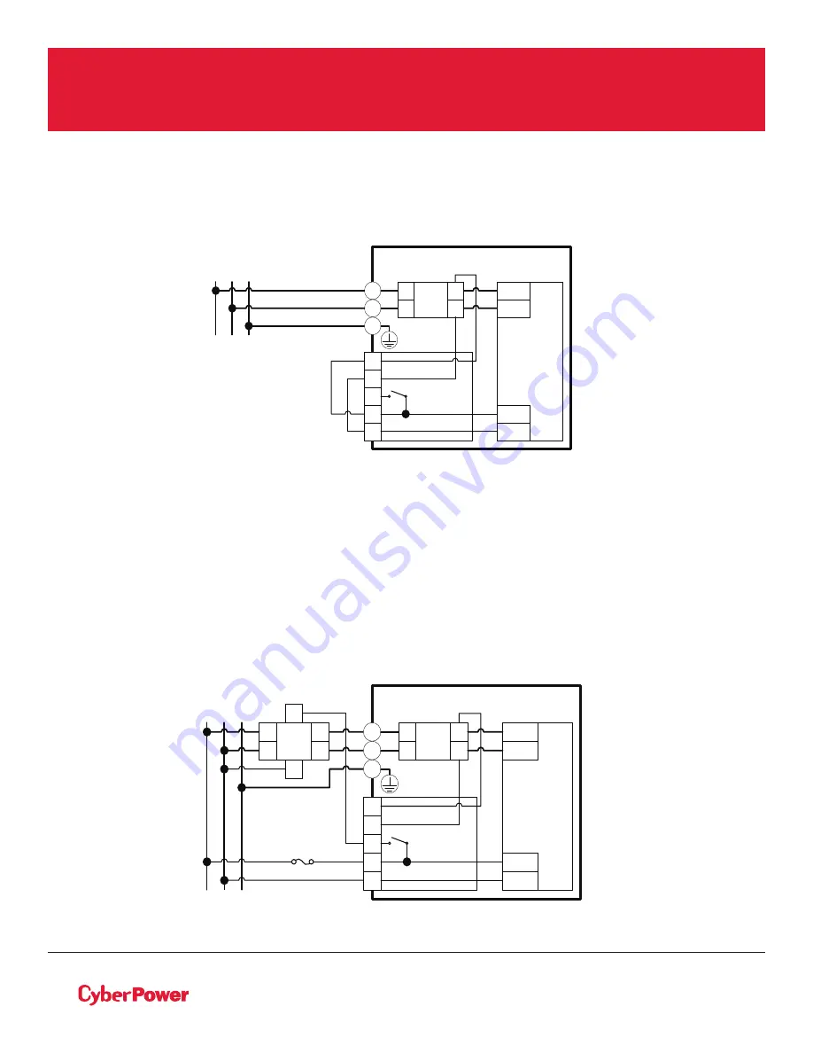
WITHOUT BACKFEED PROTECTION CONFIGURATION
1. Hardwire the input terminals as shown in the following diagram.
2. Do not remove the interconnection wires (Jumper1 / Jumper2) on “
Backfeed Protection Connector
”.
WITH BACKFEED PROTECTION CONFIGURATION
1. Connect a user supplied external isolation device (Magnetic Contactor) upstream and outside the UPS
and capable of supporting the UPS input current.
2. Remove the interconnection wires (Jumper1 / Jumper2) on “
Backfeed Protection Connector
”.
3. Hardwire the input terminals and “
Backfeed Protection Connector
” as shown in the following diagram.
4. The external isolation device must be installed in the Mains path.
UPS
L1
L2
PSDR
AC-L1
AC-L2
IP-L1
IP-L2
Backfeed
1
2
4
5
3
L1
L2
I/P
EMI
L1
L2
L1 L2 PE
Mains
PE
Jumper2
Jumper1
UPS
L1
L2
PSDR
AC-L1
AC-L2
IP-L1
IP-L2
Backfeed
1
2
3
4
5
MC
L1
L2
L1
L2
A1
A2
I/P
EMI
L1
L2
L1
L2
L1 L2 PE
Mains
PE
2A Fuse
(Slow Blow)
MAINTENANCE BYPASS MODULE
INSTALLATION CONT.


