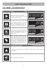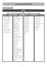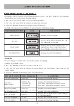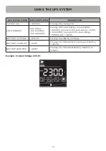
11
OVERVIEW
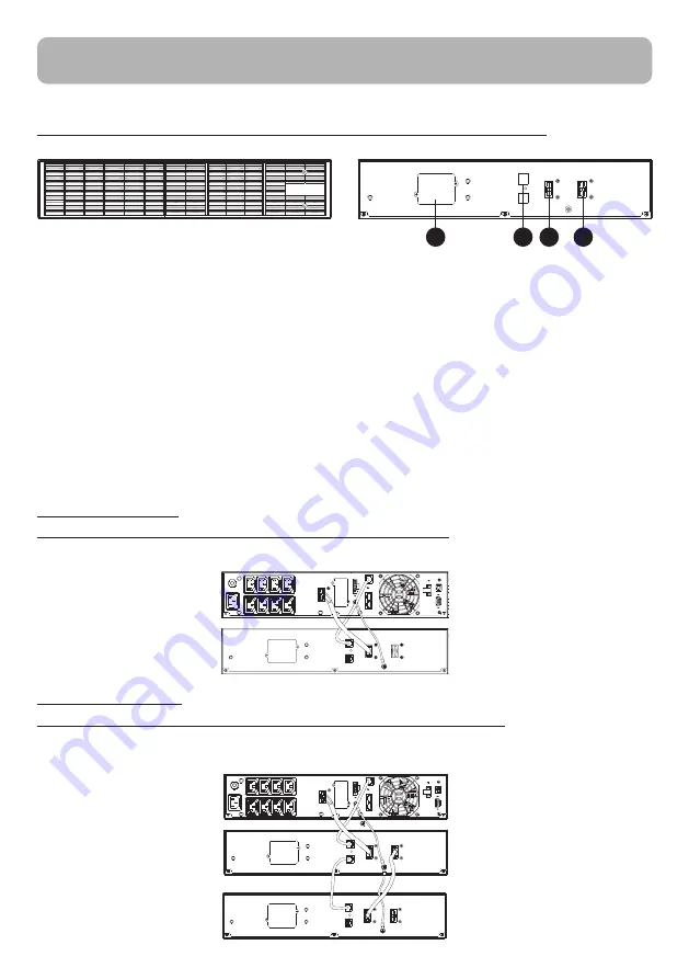
1. Input Connector
Use this input Connector to connect the Battery module to the Power module or to the next
Battery module.
2. On-board Replaceable Fuse Cover
Replaceable fuse is accessible from the rear panel. It must be done by qualified personnel.
3. Output Connector
Use this output connector to daisy chain the next Battery module. Remove the connector
cover for access.
4. Automatic Detection of Extended Battery Module Connector
Connect to UPS for automatic detection of battery modules.
CONNECTION 1:
POWER MODULE WITH ONE BATTERY MODULE
Use the battery cable of the Battery module to connect the Battery module to the Power module.
CONNECTION 2:
POWER MODULE WITH MULTIPLE BATTERY MODULES
Step 1: Connect the first Battery module to the Power module via battery cable.
Step 2: Use the battery cable to connect the second Battery module to the first Battery module.
BATTERY MODULE FRONT/REAR PANEL DESCRIPTION
BPSE24V40ART2U/BPSE48V40ART2U/BPSE72V40ART2U
1
2
4
3


