9
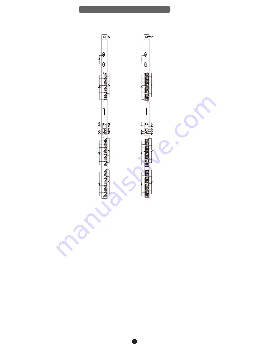
Product Features (0U 30/32A Models)
Front Panel Description
NEMA Type IEC Type
24
22
23
20
21
18
19
BANK 2
17
13
14
15
16
12
91
01
1
67
8
12
34
5
BANK 1
BANK 2
(20A)
BANK 1
(20A)
- Critical - Wa
rnin
g
- Norma
l
Link
Tx/R
x
In / ENV
USB
Out
Serial
En
te
r
Select
BANK 1
M
BANK 2
(20A)
BANK 1
(20A)
- Critical - Wa
rnin
g
- Normal
Link
Tx/R
x
In / ENV
USB
Out
Serial
En
te
r
Select
12
34
BANK
1
56
7
8
91
01
11
21
31
41
5
16
17
18
BANK
2
19
20
21
22
23
24
BANK
1
M
A. AC Inlet/ AC Power Cord - Used to connect PDU to utility
power or UPS.
B. Outlet Indicator (switched series only) – Indicates if the outlet
is providing power to connected equipment.
C. Status Indicator - Indicates the condition of the PDU (eg. load
or environment status).
D. Multifunction LCD Readout - Displays various PDU
information such as power and load condition.
E. Ethernet Port - Used to connect PDU to the network.
F. ENVIROSENSOR/ Daisy Chain (In) Port (RJ45 modular port)
- Used for ENVIROSENSOR or chaining to previous PDU.
G. USB Port - Used to upgrade the firmware via a flash drive.
H. AC Output Receptacles - Provides power for connected
equipment.
I. Serial Port (RJ45 modular port) - Used to connect to a PC
and control the PDU locally via SSH/Telnet.
J. Daisy Chain (Out) Port - Used for chaining to next PDU.
K. Select Button - Used to control the LCD screen and toggle
through the available information options.
L. Enter Button - Used to choose selected items, enter to next
level menu or return to previous menu.
M. Circuit Breaker – Provides overload protection.


