Operations Guide
931281I
CyberData Corporation
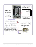
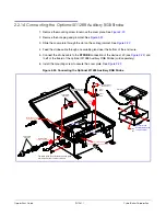
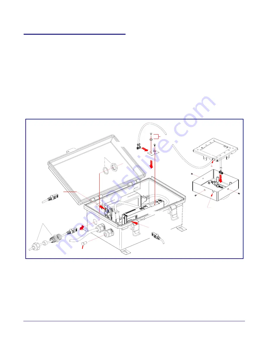
2.2.14 Connecting the Optional 011288 Auxiliary RGB Strobe
1. Remove the mounting screw to remove the cover plate. See
2. Remove the hole plug and grommet. See
.
3. Slide the cover plate through the slot on the cable grommet. See
4. Feed the strobe cable through an available gland near the bottom of the enclosure.
5. Connect the strobe cable to the
STROBE
connection of the device at J9 (see
to
J1
of the board of the optional 011288 Auxiliary RGB Strobe (sold separately).
6. Install the mounting screw to secure the cover plate. See
.
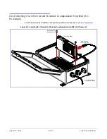
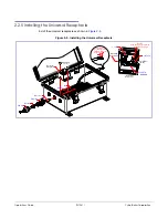
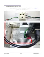
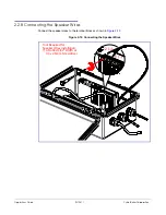
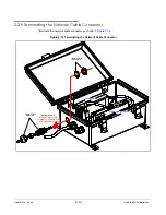
Figure 2-22. Connecting the Optional 011288 Auxiliary RGB Strobe
Cable
Slot
Remove Hole Plug
and Grommet
Cover
Plate
Slide Cable Grommet
into Cover Plate Slot
Backplate
Network Cable
Paging Amplifier Assembly
RGB Strobe Assembly
Cable Gland
Assembly
Cable Gland
Assembly
Cable Gland Plug
Shield Unused Gland
from Element
Cover
Screw
Power Injector
Exit
J1
to
J1
to Power Injector (IN)
to
STROBE
Network Port on Paging Amplifier
Power Injector (OUT)
Network Patch Cable to
Network Patch Cable to
Optional 011288
Auxiliary RGB Strobe
(sold separately)
The cable gland plug shields the unused gland
from dust and other external elements
(J9)
Summary of Contents for InformaCast Enabled 011406
Page 80: ...Operations Guide 931281I CyberData Corporation Figure 2 41 SSL Configuration Page ...
Page 81: ...Operations Guide 931281I CyberData Corporation Figure 2 42 SSL Configuration Page ...
Page 90: ...Operations Guide 931281I CyberData Corporation Figure 2 47 Audiofiles Page ...
Page 91: ...Operations Guide 931281I CyberData Corporation Figure 2 48 Audiofiles Page ...


