background image

Chapter 6

:

Replacing Components

140

SE 300™ Ultra Hardware Reference

Replacing Leveling Feet

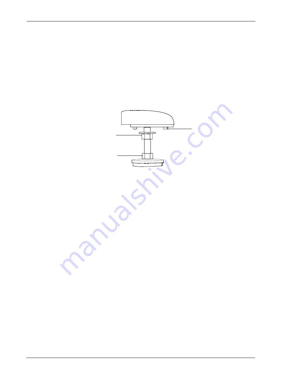
To replace leveling feet

1. Support the SE 300 Ultra frame on an appropriately-sized jack.

2. Remove the two M8 screws that secure the plate and foot assembly to the frame.

3. Replace the damaged part(s).

4. Reassemble the foot assembly onto the frame.

5. Adjust the leveling foot as needed to align the SE 300 Ultra with the conveyors (see page 29 

for details).

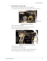
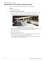
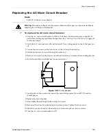
Figure 109.

Leveling Foot

Locking nut

Adjustment nut

M8 screws 

Summary of Contents for SE 300 Ultra

Page 1: ...SE 300 Ultra Hardware Reference ...

Page 2: ...otice CyberOptics Corporation may make improvements or changes in the products described in this publication at any time The following are trademarks or registered trademarks in the United States CyberOptics SE 300 Ultra owned by CyberOptics Corporation Microsoft Windows XP owned by Microsoft Corporation Pentium owned by Intel Corporation SE 300 Ultra Hardware Reference Part Number 8010658 Revisio...

Page 3: ...omponents 12 SE 300 Ultra Unit 14 SE 300 Ultra Electronics Drawer 17 System Specifications 19 Performance Specifications 20 Computer Requirements 20 System Requirements 21 Dimensions 22 3 Installation 25 Unpacking the SE 300 Ultra System 26 Choosing a Location 27 Installing the System 27 Installing the Light Pole 28 Positioning the SE 300 Ultra System 29 Install the Computer Hardware 30 Connecting...

Page 4: ... the System 60 Moving the SE 300 Ultra System 61 Disconnecting the System 61 Bypassing the SE 300 Ultra System 62 4 Running an Inspection 65 Setting Up an Inspection 66 Changing the Interface Language 66 Opening an SRFF File 67 Starting an Inspection 68 Stopping an Inspection 68 Using Defect Review 69 Defect Review Window Controls 70 Defect Review Window Areas 71 Using the Full User Interface 75 P...

Page 5: ...ibution Board 108 Replacing the Auto Width Distribution Board 109 Replacing a Power Supply 110 Replacing Fans 112 Replacing Fuses 113 Computer Components 115 Replacing Cards 115 Conveyor Components 118 Replacing the Conveyor Clamp Spring Fingers 118 Replacing the Conveyor Clamp Air Fittings 119 Replacing the Conveyor Clamp Hall Effect Switch 121 Replacing the Conveyor Clamp Cylinder 122 Replacing ...

Page 6: ...Limited Software Warranty 147 U S Government Restricted Rights 147 Updates 148 CyberOptics Terms and Conditions of Sale 148 Third Party Software 148 Non Warranty Services 149 Spare Parts Lists 150 8 Diagrams and Error Messages 153 Safety Circuit Block Diagram 154 Electrical System Block Diagram 155 AC Wiring Functional Diagram 156 Digital I O Connector Pinout 157 Digital I O Indicators 158 System ...

Page 7: ... of solder paste inspection process Documentation Documentation for the SE 300 Ultra solder paste inspection system consists of the following information SE 300 Ultra Hardware Reference Provides an overview of SE 300 Ultra components instructions for how to install and maintain the SE 300 Ultra system parts replacement information and system specifications Solder Paste Inspection Online Help Provi...

Page 8: ... and leave a voice mail message CyberOptics guarantees that all voice mail messages will be responded to during the next CyberOptics business day For calls outside the United States call the CyberOptics Minneapolis Office USA at 763 542 5000 Fax Communication You can fax service issues or problem descriptions to CyberOptics Service and Support staff CyberOptics guarantees that all fax transmission...

Page 9: ...CyberOptics Corporation 1 Safety Safety Guidelines 2 Safety and Conformity Labeling 4 ...

Page 10: ...300 has an electrostatic discharge plug on the front of the machine by the power buttons Be sure the SE 300 Ultra is properly grounded through the power connection To avoid electric shock provide an earth ground connection Do not lean on the safety enclosure or the safety enclosure frame Do not remove the safety enclosure or disable the safety interlock mechanisms Do not run the system with side p...

Page 11: ...terlock The SE 300 Ultra is equipped with a safety interlock switch on the top enclosure hood When the hood is not securely closed all motion is disabled See Figure 16 on page 16 for the location of the safety interlock To reengage the safety interlocks 1 Close the safety enclosure 2 Press the green ON button to reengage the system 3 Close the Output palette optional Indicator Lights In both the T...

Page 12: ...emoved Lockout tagout before servicing Figure 1 Pinch Point Warning Label The AC input rating label is located on the AC mains disconnect box Figure 2 AC Input Rating Label The pressurized device label is located near the air regulator The maximum air regulator pressure is 100 psi The label text says CAUTION Pressurized device Release air pressure before servicing Figure 3 Pressurized Device Label...

Page 13: ... off and lock out system power before servicing Figure 4 Hazardous Voltage Label On Electronics Drawer The read technical manual label is located on the front of the electronics drawer The label text says WARNING To avoid injury you MUST read and understand technical manual before servicing this machine Figure 5 Read Manuals Label The protective earth ground label is located on the inside of the e...

Page 14: ...l is located inside the safety enclosure on the cast polymer granite base near the conveyors In addition a printed EU Declaration of Conformity is shipped with each system If a new copy is required contact CyberOptics Customer Service Figure 8 CE Conformity Label Manufacturing Information Conformance The Manufacturing Information and CFR Conformance label is located inside the safety enclosure on ...

Page 15: ... not view the laser beam or its specular reflection directly with optical equipment that is insufficiently filtered Wear proper eye protection if the laser beam or a specular reflection creates a potential eye hazard Do not place specular mirror like surfaces within the laser beam path Obtaining More Laser Safety Information ANSI specification number Z136 1 1993 can be obtained from the Laser Inst...

Page 16: ...ra sensor indicate compliance with CDRH and IEC 825 regulations Figure 10 Caution Laser Symbol The laser radiation label text says Laser radiation Do not stare into beam Class 2 Laser product IEC 825 1993 Figure 11 Laser Radiation Label LASER RADIATION DO NOT STARE INTO BEAM CLASS 2 LASER PRODUCT IEC 825 1993 ...

Page 17: ...x power 640 670 nm wave length Class II laser product Figure 12 Laser Power Label The avoid exposure label text says Avoid Exposure Laser radiation is emitted from this aperture Figure 13 Avoid Exposure Label CAUTION LASER RADIATION DO NOT STARE CLASS II LASER PRODUCT 1 0 mW max power AVOID EXPOSURE LASER RADIATION IS EMITTED FROM THIS APERTURE ...

Page 18: ...Chapter 1 Safety 10 SE 300 Ultra Hardware Reference ...

Page 19: ...on 2 System Overview Introduction 12 SE 300 Ultra System Components 12 SE 300 Ultra Electronics Drawer 17 System Specifications 19 Performance Specifications 20 Computer Requirements 20 System Requirements 21 Dimensions 22 ...

Page 20: ...ft to right or right to left Digital Input Output Connector 15 Connection for an external device such as a separate conveyor Electronics Drawer 15 The electronics drawer contains the computers and other electronics that control the system See page 17 for more details Emergency Manual Override EMO 14 Stops all of the system s moving parts Ethernet Connector 15 Connection to local area network 10Bas...

Page 21: ...wer connections and electronics drawer Sensor 16 Measures the height volume and area of the solder pads defined for a given location The sensor moves along the X axis stage Serial Connector 15 Connection for a serial device such as a barcode reader Signal Light Pole 14 Indicates the SE 300 Ultra system status based on user configuration SMEMA Connectors 15 Connected to upstream and downstream equi...

Page 22: ... 14 through 16 show the SE 300 Ultra system components described on the previous pages Figure 14 SE 300 Ultra Front View Signal light pole Keyboard and trackball Flat panel display Safety enclosure hood Leveling feet Safety enclosure front door Power buttons Emergency Manual Override EMO ...

Page 23: ... 300 Ultra System Components Figure 15 SE 300 Ultra Inside Front Door Upstream Downstream Network Digital I O Barcode Computer AC main power circuit breaker Electronics drawer Air regulator Conveyor direction switch Interface panel ...

Page 24: ...Chapter 2 System Overview 16 SE 300 Ultra Hardware Reference 1 Figure 16 SE 300 Ultra Sensor and Conveyor 1 Left conveyor section Middle conveyor section Right conveyor section Sensor Safety Interlock ...

Page 25: ...dows Pentium 4 based microprocessor that provides the user interface The computer contains a CD ROM R W drive and two 3 5 inch disk drives The computer provides parallel serial USB and network connections Conveyor Speed Control Used to set the inbound load and outbound unload conveyor speeds to match your line speed Digital Input Output Modules and Rack Provides isolation for digital I O signals D...

Page 26: ...r supplies 3 AC power distribution board with fuses Fans Distribution board inside front of drawer Relay board Digital Input Output modules and rack X and Y axis motor controllers amplifiers Pneumatic solenoids AC filter Conveyor speed control Computer Cable breakout board inside front of drawer ...

Page 27: ...nent Clearance 25 4 mm 1 in Maximum Board Weight 1 kg 35 oz Maximum Board Warp 2 of PCB diagonal or 6 35 mm 0 25 in total Operational Specifications Conveyor Speed Range 150 450 mm sec 5 9 17 7 in sec Maximum Inspection Area 508 503 mm 20 19 8 in Field of View 10 20 mm 0 39 0 79 in Maximum Pad Size in FOV 5 10 mm 197 394 mils X and Y Pixel Size 40 microns 1 6 mils High speed 20 microns 0 79 mils H...

Page 28: ...ou can run the Teach application on a desktop computer that meets the following minimum requirements Table 5 Desktop Computer Minimum Requirements Processor Intel Pentium 4 processor RAM 256 MB recommended Disk Space available 1 GB to accommodate quilt image for 20 x 20 in panel Video card Minimum Recommended 32 MB memory 64 MB memory OpenGL acceleration Monitor resolution 1024 x 768 24 bit color ...

Page 29: ...n Coordination Pollution degree 2 Installation Category overvoltage category Category III Power Requirements Hard wired single phase 100 130 VAC 15 amp 60 Hz 50 Hz 220 240 VAC 10 amp 60 Hz 50 Hz Permitted Voltage Drops 90 V for 100 130 VAC 200V for 220 240 VAC Peak Operating Current 12 amps Compressed Air Clean dry air 80 100 psi 4 cfm Quick disconnect connection Internal Branch Circuit Fuses Nine...

Page 30: ...Chapter 2 System Overview 22 SE 300 Ultra Hardware Reference Dimensions Figure 18 SE 300 Ultra Front View 52 cm 21 in 136 cm 54 in Adjustable 8 18 cm 3 7 in 88 cm 35 in 140 cm 55 in 98 cm 38 5 in ...

Page 31: ...CyberOptics Corporation 23 Dimensions Figure 19 SE 300 Ultra Side View 140 cm 55 in 88 cm 35 in 95 cm 37 in 79 cm 31 in 83 cm 33 in ...

Page 32: ...Chapter 2 System Overview 24 SE 300 Ultra Hardware Reference Figure 20 SE 300 Ultra Top View 125 cm 49 in 185 cm 73 in ...

Page 33: ...n System Power 37 Connecting to a Network 38 Adjusting the Panel Sensors 40 Adjusting the Panel Lifter 41 Manually Adjusting the Conveyor 43 Connecting to an External Device 51 Setting Up System Security 53 Verifying System Accuracy 58 Shutting Down the System 60 Moving the SE 300 Ultra System 61 Bypassing the SE 300 Ultra System 62 ...

Page 34: ...tra Packing Crate 3 Pry off the side panel from the crate where you removed the bolts 4 Remove the packing foam and unload the accessory boxes 5 Loosen and remove the 10 bolts around the bottom perimeter of the crate The bolts are marked with blue paint 6 Slide the crate off the platform 7 Remove the bolts from the lock down plate located at each of the system s leveling feet 8 Remove any remainin...

Page 35: ...Installing the System Installing the SE 300 Ultra system consists of the general steps listed below Each step is described in more detail on the following pages Attach the light pole Position and level the system with conveyor Attach the keyboard trackball tray Attach the monitor Connect the air supply Connect SMEMA cables Install the sensor Wire the system for power Caution The SE 300 Ultra is a ...

Page 36: ...an upright position and insert the threaded end of the pole into the hole on top of the enclosure 2 Open the safety enclosure and tighten the bolt inside the enclosure so that the light pole is firmly attached to the unit 3 Connect the light pole cable to the available cable connector tied to the frame Figure 22 Light Pole Installation ...

Page 37: ...t nut Turn the nut clockwise to raise the unit Turn the nut counter clockwise to lower the unit Figure 23 Leveling Foot 4 Use a level or machine height measurements to make sure that the system is level 5 Manually slide a panel through the incoming and outgoing conveyor sections to make sure that the SE 300 Ultra conveyor rail is properly aligned The panel should pass from the upstream conveyor th...

Page 38: ...h the keyboard mounting arm to the right side of the frame using four M6 x 1 0 x 16 socket head screws 2 Attach the tray to the mounting arm using two M5 x 6 screws 3 Attach the Monitor to the plate on the mounting arm using four M4 x 0 7 x 10 button head screws Figure 24 Keyboard Trackball Mounting Hardware Monitor screws 4 places ...

Page 39: ...ounting arm with cable ties and anchors Connecting the Air Supply To connect air supply to SE 300 Ultra 1 Make sure that the air line to the SE 300 Ultra is unpressurized 2 Open the front door of the safety enclosure and locate the air regulator Figure 25 Air Regulator 3 Push the air hose connector onto the air regulator quick connect fitting 4 Turn the knob at the top of the air regulator to set ...

Page 40: ...2 Locate the SMEMA connectors on the interface panel located on the lower right side of the machine Figure 26 SMEMA Connectors 3 Route the SMEMA cables through the bottom of the SE 300 Ultra unit 4 Connect the upstream cable to the upper connector 5 Connect the downstream cable to the lower connector Downstream SMEMA connector Upstream SMEMA connector ...

Page 41: ... of the mounting plate located on the Z stage 2 Pivot the sensor to align with the top pin of the mounting plate Figure 27 Mounting Plate on the Z stage Caution Make sure the SE 300 Ultra system power is off before you install the sensor The sensor will be damaged if you connect it to the system when power is on Bottom pin Top pin ...

Page 42: ...he plate using one 6 mm screw on the front and two on the rear Figure 28 Back Plate Screws and Cable Connection 4 Connect the sensor cable to the connector on the back of the sensor and tighten the two small screws Figure 29 Sensor Installed Damper Assembly 6 mm Screws Sensor connector ...

Page 43: ...y enclosure above the air regulator on the right side of the unit Figure 30 Location of Junction Box 3 Loosen two screws on the front of the box 4 Slide the Junction box cover to the right to remove it Caution Prior to wiring the system make sure that the AC main power supply is turned off and locked off i Notes You must have a readily accessible AC main disconnect and a protective device in the f...

Page 44: ... to the pig tail wires on the junction box cover 8 Connect the ground wire to the ground bar located at the back of the Junction box Figure 32 Junction Box Cover Removed front view 9 Replace the Junction box cover 10 Tighten the two screws on the front of the box System connection L1 pig tail L2 N pig tail Box cover Caution If the ground is not properly connected the entire machine chassis will fl...

Page 45: ...cs drawer 2 Push the green button on the front of the unit to turn on the power to all system hardware 3 Turn on the power to the monitor Figure 33 AC Main Circuit Breaker Location i Note Do not open the Solder Paste Inspection application until after the lights on the signal light pole have turned on and then off When you first start up the SE 300 Ultra system the internal computer initializes th...

Page 46: ...e SE 300 Ultra system to a Local area network LAN Determine which Ethernet card should be configured for LAN connection Configure the correct Ethernet card for LAN connection To connect the SE 300 Ultra system to a network 1 Open the front door of the safety enclosure 2 Connect the network cable to the Ethernet connection on the front of the interface panel located to the right of the electronics ...

Page 47: ...l tab select the Internet Protocol TCP IP connection and click Properties The adapter with the following IP address is used for the Realtime computer IP Address 10 10 10 1 Subnet mask 255 255 255 252 If the TCP IP properties are set to obtain an address automatically or is not set to the address above you can use this adapter for your LAN Configuring the LAN Connection Use the Windows network tool...

Page 48: ... the cable ties securing the sensor cables 2 Loosen the mounting screws on the side of the panel sensor Figure 35 Middle Conveyor Section Panel Sensor Figure 36 Right and Left Conveyor Section Panel Sensor 3 Slide the panel sensor along the rail in the Y axis to the preferred position then tighten the screws 4 Secure the cables with cable ties so that they do not drag during X and Y axis motion i ...

Page 49: ... fiducials using the Panel Options properties in the SRFF file to improve the measurement accuracy However programming local fiducials will increase the inspection time by approximately 1 to 2 seconds per fiducial You can adjust the position of the panel lifter or remove it to accommodate a particular panel You may need to remove the panel lifter to adjust the conveyor section for boards less than...

Page 50: ...es Use magnetic support pins to support large panels Position the pins so they contact the board on a clear area Panel lifter pins must not be positioned within 5 mm of a panel cutout otherwise the system might rescan the panel frequently to adjust for changes in panel warp If the system rescans panels more frequently than expected check the panel lifter pin positions and adjust them as necessary ...

Page 51: ...ill return to the width of the center section If you make manual adjustments the system will prompt you whether to save the new width to the file when the SRFF is closed To adjust conveyor width 1 Open the top cover of the safety enclosure 2 Locate the conveyor adjustment dials on the front conveyor rail 3 Slide the conveyor locking mechanism on the middle and one of the two side conveyor sections...

Page 52: ...if the panel does not move smoothly along all of the conveyor sections To set conveyor direction 1 Open the front door of the safety enclosure 2 Locate the conveyor direction switch on the front section of the electronics drawer Figure 39 Conveyor Direction Switch Turn the switch to the LEFT position to set conveyor direction right to left Turn the switch to the RIGHT position to set conveyor dire...

Page 53: ...d of the external conveyor on the left side of the SE 300 system Use the Right control to match the speed of the external conveyor on the right side of the system 4 Close the electronics drawer and the front door of the safety enclosure 5 Slide the panel lifter support under the back rail of the conveyor 6 Reconnect the cable track to the panel lifter support 7 Place the panel lifter support on th...

Page 54: ...oving the panel lifter and connecting a different opto for the center conveyor section To remove the panel lifter 1 Turn off the air flow to the panel lifter Lift Up Lift Down Figure 41 Air Flow Controls 2 Lift the top plate of the panel lifter i Note Removing the panel lifter and the sensor attached to it requires recalibrating the conveyor to a different opto Contact CyberOptics before adjusting...

Page 55: ...Figure 42 Panel Lifter 4 Clip the inductor sensor cable tie 5 Loosening the bracket screw and remove the sensor from the bracket Figure 43 Inductive Sensor Adjust lifter position for access by turning knob Disconnect hoses from lifter cylinder Loosen bracket screw and pull sensor out of the bracket Clip the cable tie ...

Page 56: ...ket from the lifter Figure 44 Inductive Sensor Bracket 7 Disconnect the cable track by loosening the screw that secures the bracket to the panel lifter support Figure 45 Cable Track Connection Rear View of Panel Lifter Loosen bracket screws and remove bracket Loosen screw to disconnect the cable track ...

Page 57: ...ock enough to work it off of the rail and out from underneath the lead screw Figure 46 Plastic Bearing Block Screws 9 Remove the entire panel lifter assembly from the conveyor 10 Use a cable tie to secure the loose cable track near the point where the air flow tubes enter the cable track Loosen these screws enough to work the support bar and block out from underneath the lead screw ...

Page 58: ...ocated on the right side of the center conveyor section The cable connection is labeled RIGHT PROX 2 Connect the RIGHT PROX cable to the sensor mounted on the conveyor rail Figure 47 Right Proximity Sensor Connect this sensor to the RIGHT PROX cable Disconnect this sensor to run 35 mm panels RIGHT PROX cable ...

Page 59: ...urn the AC main circuit breaker to OFF to shut down power to the entire system 4 Open the front door of the safety enclosure 5 Connect the external device to the digital input output connection on the front of the interface panel on the right side of the electronics drawer Figure 48 Digital Input Output Connector 6 Close the front door of the safety enclosure 7 Turn the AC main circuit breaker to ...

Page 60: ...ct Response Group 5 Select Response Group click Add Properties and select Outputs Response 6 Select Outputs Response and set Output 1 and to ON Note Outputs 0 1 and 2 can conduct current current rating 0 25 amp but only Outputs 1 and 2 have over current protection 7 Save and close the SRFF file To turn off Output 1 after a new panel is loaded 1 In the Solder Paste Inspection open the SRFF file 2 S...

Page 61: ...tra can use one of the default logons password CyberOptics The default setup allows full access to all SE 300 Ultra features for all users except for the Security Setup feature Only the Supervisor logon has rights to change the Security Setup by default The default setup also includes an Auto logon feature so that when any of the default system logons are used a separate SE 300 Ultra logon is not ...

Page 62: ...and locate the two sample text files provided passwords txt and groups txt The pathname to this directory is c Program Files CyberOptics SE 300 System Software Security Utilities 2 Open the passwords txt file in a text editor 3 Replace the sample names and passwords with your system login names and passwords Use the comma as a delimiter For example Weston CyberOptics Frankie CyberOptics Leslie Cyb...

Page 63: ...ialog box The program runs two separate batch files secPwords bat and secGroups bat to load the user names and passwords into the appropriate groups No user intervention is required To add the same user information to additional systems 1 Copy the modified passwords txt and groups txt files to the next system s security directory c Program Files CyberOptics SE 300 System Software Security Utilitie...

Page 64: ...s to identify an inspection area in which to search for a fiducial Solder Paste Inspection File Save Allows group members to save changes to the panel SRFF file and the Standard Definition Library DEF file Teach and Solder Paste Inspection Security Secure Assignments Allows group members to change the Secure Area assignments Teach and Solder Paste Inspection Status Bar Units Change Allows group me...

Page 65: ...rom the list You should have the following four groups from which to choose Supervisors Engineers Lead Operators and Operators 3 To add access to a Secure Area select the name from the Unassigned list and click Add 4 To change access to a Secure Area select the name from the Assigned list and click Remove Then add the Secure Area to a different group as described in steps 2 and 3 above 5 Click on ...

Page 66: ...l is shipped in a hardwood box that should be used for permanent storage Each tool is engraved or marked with a serial number Hold the certification tool by the edges as you use it and keep it free of oils dirt grease and dust CyberOptics Certificate of Traceability CyberOptics provides a certificate of traceability with each certification tool The certificate includes the serial number and the ce...

Page 67: ...the conveyor as you would a board 6 Click to open the Failure Report and monitor the feature level results If the inspection results appear in green in the Panel View and there are no failures in the Failure Report the SE 300 Ultra system is accurate within specification If any of the inspection results appear in red in the Panel View and there are failures in the Failure Report the SE 300 Ultra s...

Page 68: ...h the red button on the front of the unit This removes power between the AC main circuit breaker and the system hardware 3 Open the front door of the safety enclosure and set the AC main circuit breaker to OFF to shut down power to the entire system including the internal computer Caution Turning off power without first shutting down Windows may cause a loss of data ...

Page 69: ...ressure on the air line 4 Disconnect any additional external connections to the computer such as printers 5 Disconnect external connections to the interface panel such as the network SMEMA or I O cables if used 6 Disconnect the air line from the air regulator 7 Make sure the safety enclosure is closed so that the door does not swing open when you move the system Caution The SE 300 Ultra unit weigh...

Page 70: ...s to run continuously Kit Contents SMEMA bypass cable 2 conveyor bypass connectors one left to right and one right to left To pass SMEMA signal through the SE 300 Ultra 1 Shut down Windows then push the red button on the front of the unit 2 Open the front door of the safety enclosure and pull the electronics drawer open 3 Turn the AC main circuit breaker to OFF to shut down power to the entire sys...

Page 71: ...Open the electronics drawer 2 On the distribution board locate connector C1 in the upper right hand corner 3 Disconnect the conveyor control cable P N 8001978 that is plugged into connector C1 Figure 50 Electronics Drawer Figure 51 Distribution Board C1 Location Relay board Distribution board Location C1 ...

Page 72: ... the conveyor runs right to left 5 Connect the 8 pin connector on the conveyor bypass cable into J44 on the relay board next to the Safety OK LED Figure 52 Relay Board J44 Location 6 Close the electronics drawer and the safety enclosure 7 Turn AC main circuit breaker to ON to turn on power to the system If the EMO button is pushed in pull it out then press the green ON button to engage the system ...

Page 73: ...ation 4 Running an Inspection Setting Up an Inspection 66 Opening an SRFF File 67 Performing a Reference Scan 75 Starting an Inspection 68 Stopping an Inspection 68 Using Defect Review 69 Using the Full User Interface 75 ...

Page 74: ...berOptics Process Insight or other third party SPC tools Inspection data can be saved as XML HTML text or comma delimited CSV text files to support remote monitoring and analysis Set up responses to system events such as clearing alarms when a panel is loaded Change the units for measurement data Changing the Interface Language Solder Paste Inspection Control can be run in Simplified Chinese Tradi...

Page 75: ...at the conveyor locks are disengaged and then click OK To open a file using the handheld barcode reader 1 Make sure that the SRFF folder is identified in the Tools Options File Handling tab 2 Scan Open SRFF File or select Scan from the File menu 3 Scan the barcode s for the panel and lot number These barcodes are provided in the work order In some cases the panel description SRFF file may already ...

Page 76: ...eives Board Available SMEMA signal from the upstream machine it moves the panel into position clamps it and begins the inspection process Stopping an Inspection To stop an inspection Click in the Control window to stop the SE 300 Ultra after the current panel is inspected and hold the panel The system stops until you click or Click in the Control window to pass panels through the SE 300 Ultra with...

Page 77: ... save an image of the Defect Review window pass a panel or fail a panel The basic parts of the Defect Review window are identified below and described on the following pages For more information see the Solder Paste Inspection Control online help Figure 53 Control Window Defect Review 3D Shaded Image Panel Image Defect List Inspection Results Controls Height Map and Video Image ...

Page 78: ...urns off the red light Resetting alarms does not clear any output signal responses Previous Defect Displays the previous defect Next Defect Displays the next defect Pass Board Passes the board and returns to the Main Window Fail Board Fails the board and returns to the Main Window Save Defect Image Saves an image of the current window to the images directory within the SRFF file structure Close Cl...

Page 79: ...lume and or area are too low Registration Registration bridging and or boundary violation When there is more than one defect If a location has more high categories than low the high icon is displayed If a location has more low categories than high the low icon is displayed If a location has no high or low categories the registration icon is displayed If a location has mix of categories with the sa...

Page 80: ...e image and color variations to show the paste shape A color key in the lower left portion of the window correlates the colors in the image with paste height The color key automatically scales to the paste heights found in the current field of view A transparent cube covers the selected feature showing the optimum paste coverage ...

Page 81: ... Toggle between the views by clicking on the inspection data area Data View The Data view shows data for the following Height measured height target height low fail and high fail Volume measured volume target volume low fail and high fail Area measured area target area low fail and high fail Bridging measured bridging target and high fail Registration shows registration short and long as a percent...

Page 82: ... Map The Height Map is a representation of height values across the entire panel In the height map light areas indicate relatively higher paste values and dark areas indicate relatively lower height values Video Image The Video Image shows a grayscale image of the field of view on the current panel captured by the system sensor The field of view includes the selected feature ...

Page 83: ... Offsets option is set for the SRFF file default setting the system also measures the distance between the surface of the bare panel and the height of the copper and stores this as an offset value Offsets are subtracted from the overall solder paste height for a more accurate measurement of actual paste height To perform a reference scan 1 In the full user interface open the SRFF file if not done ...

Page 84: ...eference scan data or use existing reference scan data if found System is not ready to run a reference scan the system is in pass through mode or is not yet initialized Click OK to close the dialog box When the system is initialized and ready perform a reference scan by selecting Reference Scan from the Tools menu Failures that appear when you attempt to run a reference scan result in the followin...

Page 85: ...plication Panel view Failure report Trend charts Defect Review Panel View The Panel view shows which pads passed failed or fell below the warning tolerances The colors of the features change as a panel is inspected Before an inspection the features appear in dark red After an inspection the features appear Green if they pass Red if they fail Yellow if they fall above or below the warning tolerance...

Page 86: ...ure reports include up to 1000 lines after which the oldest data is deleted 100 lines at a time To monitor the inspection using a Failure report 1 Click Select feature location or image from the Data list The data columns in the report vary with the selected element Figure 55 Failure Report 2 Right click in the column header area to open a show hide dialog box where you can choose which columns to...

Page 87: ...e 80 The trend chart may include up to three reference lines Upper failure limit for a given measurement If a measurement exceeds this limit it is considered a failure Nominal value If the trend chart represents pad height volume or area this is the target value for a given measurement Lower failure limit If the trend chart represents pad height volume or area this is the lower tolerance for a giv...

Page 88: ...ridging Panels only for bridging Failed Features H A V Panels images and locations Failed Locations H A V Panels and images Failed Images H A V Panels only Failed Features Reg Panels images and locations for registration Failed Locations Reg Panels and images for registration Failed Images Reg Panels only for registration Height Features only Height Range Locations only Offset Long Dim Features on...

Page 89: ...w The Defect Review window contains a failure pane that lists inspection defects for the current panel and an image pane that shows where defects were found The system clears the report each time a panel is loaded Figure 58 Defect Review Window List of defects Image pane ...

Page 90: ...e At the location image and panel level when accumulations of failure counts exceed values set in the Teach application Location image and panel data are displayed for analysis only in the Solder Paste Inspection application and do not cause failures but can be used to diagnose registration problems Registration data can also be logged to a data file Checking Paste Registration Check the solder pa...

Page 91: ...ow hide dialog box where you can choose which columns to show in the report Figure 60 Show Hide Dialog 5 When the inspection finishes analyze the registration measurements in the Numeric Report and adjust the printer as necessary See Using Registration Data to Adjust the Printer on page 85 for more information ...

Page 92: ...ing a Trend Chart 1 Click on to open a Trend Chart 2 Drag the element to monitor typically the panel element into the Trend Chart window 3 Select the registration data type of interest such as Offset X Offset Y or Rotation 4 Watch for data trending out of specification as the inspection runs Registration data at the panel level does not have tolerances so the trend chart shown above does not inclu...

Page 93: ...n across the feature location image or panel measured in the X horizontal or Y vertical directions These values are calculated from feature level measurements and are expressed in the units of the SRFF file Positive X values indicate a shift to the right Negative X values indicate a shift to the left Positive Y values indicate an upward shift Negative Y values indicate a downward shift If these va...

Page 94: ... example that if the system is configured to flash a signal light and turn on a diverter conveyor when a failure is detected clicking the reset alarms button only turns off the signal light The diverter conveyor remains on until a separate event such as panel loaded resets the response Running the System in Pass Through Mode Use the Pass through mode to pass panels through the SE 300 Ultra conveyo...

Page 95: ...panels will append to that file After inspecting the good panels import the data into the Teach application where the nominal values are re calculated To import nominal solder paste values 1 Open the SRFF file in Teach 2 On the File menu select Import and then Solder Paste Inspection Data 3 Navigate to and select the data file It must have the same name as the current SRFF file with the extension ...

Page 96: ...Chapter 4 Running an Inspection 88 SE 300 Ultra Hardware Reference ...

Page 97: ...CyberOptics Corporation 5 Maintenance Periodic Hardware Maintenance 90 Sensor Maintenance 102 Software Upgrades 102 Checking RT Computer Status 102 ...

Page 98: ...at hood opens easily 3 Check for stress or cracks at hinges Caution To prevent the risk of injury shut down all electrical power to the SE 300 Ultra before starting any maintenance operations i Note CyberOptics Service and Support can provide Limited and Extended Warranties on SE 300 Ultra units Contact CyberOptics Service and Support for more information Cautions Do not lean on the top safety enc...

Page 99: ...nection where the hood spring attaches inside the hood toward the front of the machine see Figure 61 3 Use a screw driver to pry open one side of the metal clip that fits over the ball joint 4 While supporting the hood pry the ball joint open and release the hood spring from the socket 5 Repeat on the other side of the hood 6 Lift the hood open and gently rest it on the rear of the machine Figure ...

Page 100: ... the rear section Check these strips for wear and replace as necessary To replace a conveyor wear strip on the left or right section of the conveyor 1 Loosen the screws that secure the wear strip 2 Pry the wear strip off of the conveyor rail 3 Attach a new wear strip using the original screws Figure 62 Conveyor Wear Strip Front End Section Screw 2 places Wear strip ...

Page 101: ...pring fingers by removing nine nuts see also page 118 Figure 63 Center Conveyor Section 2 Insert a wrench into the hole vacated by the nuts removed above and loosen the five screws that secure the wear strip 3 Pry the wear strip off of the conveyor rail 4 Attach a new wear strip using the original screws 5 Assemble and secure the spring fingers back into the conveyor clamp Nuts 9 places Spring fin...

Page 102: ...g rails 1 Open the top cover of the safety enclosure 2 Locate the grease fittings on the X axis stage motor plate Figure 64 Figure 64 Grease Fittings 3 Pump grease into each fitting using a grease gun with a tapered nozzle fitting 4 Stop pumping when the grease overflows on the opposite side 5 Slide the X axis stage back and forth manually 6 Wipe off grease overflow Grease fittings ...

Page 103: ... middle conveyor section to one end of the Y axis 3 Apply grease to the length of the Y axis bearing rails Figure 65 Figure 65 Y axis bearing rails 4 Push the middle conveyor section to the other end of the Y axis Apply grease to the remaining length of the bearing rails 5 Slide the middle conveyor section back and forth manually Y axis bearing rails ...

Page 104: ... Lead Screw 7 Move the Z stage up and down manually If the damper is installed turn the damper to move the stage If the damper is not installed turn the lead screw from underneath the Z stage using a flat tip screw driver 8 Slide the sensor onto the bottom pin of the mounting plate 9 Pivot the sensor to line up with the top pin of the mounting plate 10 Insert the bolt s through the back of the mou...

Page 105: ...eyor Section Lead Screw 3 Adjust the width of the conveyor to the narrowest setting 4 Use your fingers to apply a small amount of grease to the portion of the lead screw behind the back rail 5 Adjust the width of the conveyor to the widest setting 6 Apply a small amount of grease to the portion of the lead screw between the front and back rails 7 Repeat this procedure for each conveyor section Lea...

Page 106: ...f the safety enclosure by turning the two large black quick connects and lifting the panel off 2 Locate the air intakes on the back of the electronics drawer Figure 68 Air Intakes 3 Remove the layer of dust covering the air intakes and wipe off remaining dust with a damp cloth 4 Replace the back panel of the safety enclosure ...

Page 107: ...re 2 Locate the air regulator inside the SE 300 Ultra on the lower right side of the unit Figure 69 Air Regulator 3 Disconnect the air supply 4 Unscrew bowl at the bottom of the regulator and take out the filter 5 Rinse the filter in warm water and let it air dry 6 Replace the filter and the bowl at the bottom of the regulator Air supply fitting Bowl with filter ...

Page 108: ... the X and Y axes Figure 70 Figure 70 Y axis Encoder Strip Figure 71 X axis Encoder Strip 3 Remove any coarse or abrasive particles with clean dry air 4 Wet a clean cloth or swab sparingly with isopropyl alcohol 5 Gently wipe the encoder strip with the cloth or swab Caution The encoder strips can be damaged by abrasive substances and solvents Follow the procedure below to avoid scratches or other ...

Page 109: ...n the top cover to the safety enclosure 2 Locate the four panel sensors near the conveyor inside the top cover of the safety enclosure Figure 72 and Figure 73 Figure 72 Right And Left Conveyor Section Panel Sensor Figure 73 Middle Conveyor Panel Sensor 3 Dampen a soft cloth with household glass cleaner Note Do not use solvents or abrasives to clean the panel sensor lenses 4 Gently wipe the panel s...

Page 110: ...ocated on the CD ROM 3 Follow the prompts on the screen to install the System Software 4 After installing the software press the Reset button on the computer to restart the RT computer Checking RT Computer Status Use the Telnet application to check the status of the RT computer To start Telnet 1 From the Start menu select Run 2 In the Run dialog box type telnet realtime and click OK 3 At the login...

Page 111: ...CyberOptics Corporation 6 Replacing Components Electronics Drawer Components 104 Computer Components 115 Conveyor Components 118 Other Components 136 ...

Page 112: ... faulty relay board and replace it with a new board Note Inspect the components and jumpers on the new board to make sure that nothing was damaged in transport 4 Secure the board with 13 M4 10 screws 5 Reconnect the cables Figure 74 shows the cable connections by cable part number on the relay board Warning To prevent the risk of injury turn the AC main circuit breaker to OFF to shut down all elec...

Page 113: ...4 8001988 8001982 8004285 or 8008310 8004284 or 8008309 8001950 8001940 8001941 8001955 8001939 8001937 8001979 8007029 8001983 8001959 8001977 8001949 8001987 8009919 or 8010544 8001966 8001983 8001956 8001978 8004329 or 8008312 8001954 8004125 or 8008311 8004585 8010552 Note indicates cables for the autowidth conveyor ...

Page 114: ...roller board to the Relay board 3 Gently pull the motor controller board from the Relay board connectors 4 Insert the new motor controller board and press it firmly into the Relay board connectors 5 Secure the four screws Figure 75 Motor Controllers on Relay Board Caution The Relay board contains components that can be damaged by static electricity Use a ground strap when handling the board to pre...

Page 115: ...he cover plate 4 Gently pull the EMO relay from the through hole connectors on the Relay board 5 Insert the new EMO relay lining up the pins on the EMO relay with the holes on the Relay board Press firmly into place 6 Secure the cover plate with a screw Do not over tighten the screw Figure 76 EMO Relays Caution The Relay board contains components that can be damaged by static electricity Use a gro...

Page 116: ...crewing the nine M4 6 screws holding the board in place 3 Secure the new board in place using nine M4 6 screws 4 Reconnect the cables Figure 77 shows the cable connections by cable part number on the Distribution board Figure 77 Distribution Board Cable Connections Caution The Distribution board contains components that can be damaged by static electricity Use a ground strap when handling the boar...

Page 117: ...Remove the Distribution board by unscrewing the four M4 10 screws holding the board in place 3 Secure the new board in place using nine M4 10 screws 4 Reconnect the cables Figure 78 shows the cable connections by cable part number on the Distribution board Figure 78 Auto Width Distribution Board Cable Connections Caution The Auto Width Distribution board contains components that can be damaged by ...

Page 118: ... to the relay board 8001544 Power Supply 60W located in the middle provides power to the sensor and the Pipeline Processor Module PPM card 8001542 Power Supply 125W located on the bottom provides power to the monitor and auxiliary power for the relay board Caution The Power Supplies contain components that can be damaged by static electricity Use a ground strap when handling the board to prevent d...

Page 119: ...e from the power supply 11 Remove the four screws that secure the power supply in the case 12 Install the new power supply and secure in place with four screws 13 Connect the ac input power cable to the power supply 14 Connect the dc output cable to the supply 15 Secure the power supply case cover with two screws 16 Secure the ground lug next to the connector 17 Attach the power supply to the chas...

Page 120: ...able 3 Slide an Allen wrench through the hole in the upper corner of the fan case to loosen the screws 4 Remove the fan 5 Disconnect the cable from the fan 6 Connect the new fan to the cable Make sure that the label on the fan and the electrical connector are facing the inside of the electronics drawer Make sure that the wires are routed through the fan case 7 Secure the fan in place with the scre...

Page 121: ... To replace a fuse on AC power distribution board 1 Remove the plastic safety cover Figure 82 AC Distribution Board 2 Using a flat tip screw driver or a fuse puller gently pry out the fuse 3 Install the new fuse 4 Install the plastic safety cover Caution Before replacing a fuse make sure that the AC main power is turned off and locked off Fuses Plastic safety cover ...

Page 122: ...114 SE 300 Ultra Hardware Reference To replace a fuse on relay board 1 Locate the fuses on the Relay board Figure 83 Fuse Locations 2 Using a flat tip screw driver or a fuse puller gently pry out the fuse 3 Install the new fuse Fuses ...

Page 123: ...to the card 5 Remove the screw holding the card to the computer case 6 Gently slide the card out of the computer case 7 Slide the new card into the computer case gently pushing it into place so that it is firmly seated in the backplane connector 8 Secure the card in place with one screw 9 Reconnect connectors to the card 10 Slide the computer back into the electronics drawer and secure it with thr...

Page 124: ...ndows Single Board Computer SBC card Galil Motion Controller card Parallel ports Serial ports RS 232 COM Video port RT SBC card Pipeline Processor PPM card Digital I O card Serial ports RS 232 COM The Windows and Real time Single Board Computer SBC cards are the same type of card See Figure 85 for the location of connectors on the computer circuit cards ...

Page 125: ...rive CN1 CN4 LPT Parallel Port SATA 1 CN5 External Mini DIN Keyboard Mouse J3 Video Port LAN1 LAN2 RJ45 PS 2 Mouse Keyboard ATXCTL Backplane to SBC USB4 IDE2 Secondary connector IDE1 Primary connector Compact Flash Card location CN4 LAN 2 State CN3 LAN1 State SATA 2 CN2 Power IrDA IR1 USB3 USB2 USB1 COM2 COM1 ...

Page 126: ...ace the conveyor spring fingers 1 Turn off all electrical power to the system 2 Remove the nine M5 nuts on the top of the conveyor clamp Figure 86 Conveyor Clamp Spring Fingers 3 Remove the spring fingers 4 Slide in the new spring fingers lining up the bolts with the holes on the top plate 5 Push the spring fingers back so its edge abuts the lip on the underside of the clamp top plate 6 Apply a th...

Page 127: ...o replace an air fitting assembly 1 Turn off air to the conveyor clamp by tightening the screws on the CLMP UP and CLMP DOWN flow controls located toward the back of the unit on the center conveyor section Figure 87 If your system does not have flow controls on the unit turn off the air pressure at the air regulator Figure 87 Air Flow Controls 2 Disconnect the air hose from the air fitting assembl...

Page 128: ...e first thread exposed 6 Attach the air fitting assembly to the conveyor clamp cylinder tightening the nut on the brass portion of the fitting Position the assembly so it does not extend beyond the top or sides of the conveyor clamp cylinder 7 Reconnect the air hose to the new air fitting assembly 8 Turn on air to the conveyor clamp by loosening the screws on the flow controls or turning on the ai...

Page 129: ... clamp cylinder using a 5 16 allen wrench Support the clamp surrounding the screw with a in wrench to avoid bending the shoulder screw 4 Flip the conveyor clamp cylinder away from the conveyor rail 5 Slide the switch out of the groove on the side of the cylinder 6 Unscrew the switch cable connector 7 Slide the new switch into the groove on the side of the cylinder 8 Flip the cylinder back up to th...

Page 130: ...nveyor rails Parts 8005753 Conveyor Clamp Cylinder 8000517 Teflon Tape To replace the conveyor clamp cylinder 1 Turn off air to the conveyor clamp by tightening the screws on the CLMP UP and CLMP DOWN flow controls located toward the back of the unit on the center conveyor section Figure 90 If your system does not have flow controls on the unit turn off the air pressure at the air regulator Figure...

Page 131: ...screw at the base using a thread locking sealant on the screw 9 Reattach the hall effect switch if removed in step 4 Use the measurements taken in step 4 to attach the switch as near the same position as possible 10 Wrap teflon tape twice around the brass ends of the air fitting assemblies leaving the first thread exposed 11 Attach the air fitting assemblies to the conveyor clamp cylinder tighteni...

Page 132: ...clamp assembly Figure 92 Conveyor Top Clamp Assembly Bolt Locations 2 Lift the top clamp assembly off of the frame and place it on the granite base 3 Locate the conveyor motor on the front rail of the conveyor section left middle or right 4 Loosen the four motor mounting screws and slide the motor to loosen the drive belt 5 Remove the drive belt Figure 93 Drive Pulley And Drive Belt 6 Disconnect t...

Page 133: ...ghten 10 Reconnect motor cable and ground wire 11 Place the drive pulley on the motor shaft Position the drive pulley close to but not rubbing against the motor mounting plate 12 Place the drive belt on the drive pulley 13 Slide motor to take up slack in the drive belt Make sure that the teeth on the drive belt align with the grooves on the drive pulley 14 Reattach the conveyor top clamp assembly ...

Page 134: ...or Belt 3 Loosen the axle screw on the tension pulley located on the back side of the front rail 4 Remove and replace the tension pulley 5 Slide the tension pulley into position under the front rail 6 Secure the pulley with two screws To replace the conveyor belts 1 Remove the top clamp assembly see steps 1 and 2 on page 124 2 Loosen the four motor mounting screws and slide the motor to loosen the...

Page 135: ...ve pulleys from square shaft 4 Remove the square shaft retaining ring at the back conveyor rail 5 Push the square shaft to the back of the machine Figure 97 Belt Configuration On Back Rail 6 Remove the back conveyor belt 7 Assemble the new belt onto the pulleys 8 Reposition the square shaft and replace the square shaft retaining rings 9 Reconnect the pulleys on the square shaft and tighten set scr...

Page 136: ...ws on each side of the motor bracket and push down on the tensioners 2 Slide the belt off of the pulleys Figure 98 Auto Width Motor Belt Center Section 3 Thread the new belt onto the pulleys and over the tensioners 4 Slide the tensioners up to apply pressure onto the pulley increasing the belt tension to approximately 1 4 play in the belt when you press downward on it 5 Tighten the tensioner screw...

Page 137: ...ket Figure 99 Auto width Motor Center Section 5 Replace the motor and reinstall the mounting screws 6 Slide the pulley onto the motor shaft until the shaft is about flush with the pulley surface 7 Slide the tensioners up to apply pressure onto the pulley increasing the belt tension to approximately 1 4 play in the belt when you press downward on it 8 Tighten the pulley set screws 9 Reinstall the b...

Page 138: ...Thread the new belt onto the pulleys and over the tensioners 4 Slide the tensioner up to apply pressure onto the pulley increasing the belt tension to approximately 1 4 play in the belt when you press downward on it 5 Tighten the tensioner screw on the side of the motor bracket i Note The auto width motor for the center section contains different software than the auto width motors for the end sec...

Page 139: ...acket Figure 101 Auto width Motor End Section 5 Replace the motor and reinstall the mounting screws 6 Slide the pulley onto the motor shaft until the shaft is about flush with the pulley surface 7 Slide the tensioner up to apply pressure onto the pulley increasing the belt tension to approximately 1 4 play in the belt when you press downward on it 8 Tighten the pulley set screw 9 Reinstall the bel...

Page 140: ... Panel Sensor To replace the panel sensors 1 Remove the two mounting screws and nut plate on the panel sensor see Figure 102 2 Clip the cable ties to free the panel sensor cable from the conveyor 3 Disconnect panel sensor cable and remove the panel sensor 4 Attach new panel sensor to the mounting bracket and secure with two screws 5 Connect panel sensor cable 6 Secure the cable ties so that the ca...

Page 141: ...onveyor Components Figure 102 Panel Sensors on Conveyor Mounting screws for 8004227 sensor Mounting bracket Middle Conveyor Section Left and Right Conveyor Sections Mounting screws Mounting bracket Mounting screws for panel sensor ...

Page 142: ...g hole Figure 103 Inductive Sensor In Panel Lifter 3 Place the new inductive sensor in the mounting hole so that it is flush with the far side of the mounting hole Position the sensor so it sees the tab on the lift plate 4 Tighten the mounting screw 5 Reconnect the inductive sensor cable 6 Check the inductive sensor for mechanical interference by manually moving the lifter a Disconnect the system ...

Page 143: ...g Figure 104 Panel Lifter Cylinder 4 Lift up on the panel lifter plate to remove it 5 Disconnect the two air hoses Note Mark the air hoses for proper installation Air connections are not interchangeable 6 Note the height of the cylinder in reference to its mounting bracket for later placement 7 Loosen two mounting screws and lift the cylinder out of the mounting bracket 8 Slide the cylinder into t...

Page 144: ... the safety interlock switch 1 Open the SE 300 Ultra hood 2 Turn two latches on the lower section of the right panel to remove the panel from the machine and gain access to the switch Figure 105 Safety Interlock Switch Access Caution Turn the AC main circuit breaker to OFF to shut down all electrical power to the SE 300 unit before starting any replacement operations See Shutting Down the System o...

Page 145: ...for color coding 10 Install the cover onto the safety interlock switch Figure 106 Safety Interlock Switch To align safety interlock switch 1 Press the green ON button to turn on system power 2 Close the hood to make sure the pin is lined up with the safety interlock switch socket To check the alignment Re engage the EMO Observe the safety circuit relays inside the electronics drawer The LEDs shoul...

Page 146: ...r regulator Figure 107 Air Regulator 3 Gently pull the air regulator down to remove it 4 Install the new air regulator 5 Turn the knob at the top of the air regulator to set the air pressure to OFF before reconnecting air 6 Screw on the plastic ring at the top of the air regulator 7 Reconnect and turn on the air supply 8 Turn the knob at the top of the air regulator to set the air pressure to 90 p...

Page 147: ...e the Junction box cover to the right to remove it 5 Remove two screws on the front cover of the Junction box to remove the mounting bracket 6 On the front of the circuit breaker loosen four screws Figure 108 Circuit Breaker 7 Gently pull out the wires to disconnect the outside line power L1 and L2 N and the system power 8 Replace the circuit breaker 9 Reassemble the mounting bracket using two scr...

Page 148: ...n an appropriately sized jack 2 Remove the two M8 screws that secure the plate and foot assembly to the frame 3 Replace the damaged part s 4 Reassemble the foot assembly onto the frame 5 Adjust the leveling foot as needed to align the SE 300 Ultra with the conveyors see page 29 for details Figure 109 Leveling Foot Locking nut Adjustment nut M8 screws ...

Page 149: ...CyberOptics Corporation 7 Warranty and Spare Parts Limited Warranty 142 Standard Software License Terms 145 Non Warranty Services 149 Spare Parts Lists 150 ...

Page 150: ...use not the fault of CyberOptics are not covered by this limited warranty and shall be at the buyer s expense CyberOptics shall not be obligated to pay any costs or charges incurred by the buyer or any other party except as may be agreed upon in writing in advance by an authorized CyberOptics representative All costs of dismantling reinstallation and freight under this warranty clause shall be the...

Page 151: ...at this product will not when used in the normal manner in any way infringe any claims of any United States or foreign patents and CyberOptics will not indemnify the buyer or its customers for any claims brought against the buyer or its customers for infringement of any such patents In any event the buyer agrees that CyberOptics shall not be liable for infringement and the buyer shall fully indemn...

Page 152: ...amine the problem and make the necessary repairs or replacements When on site repairs are not possible CyberOptics will provide a prompt solution to the problem You must telephone fax or e mail CyberOptics for a written estimate on all non warranty service events For on site service you are required to have a purchase order number before service is scheduled On parts or software covered under anot...

Page 153: ... terms and conditions Effective Date means the earlier of You opening the package or envelope containing the Software if applicable You first using the Software or the shipment of the CyberOptics System containing the Software Site means a facility or location with a specific unique address at which You have an installed CyberOptics System of the type covered in the Programming Software Software m...

Page 154: ... You agree to use your best efforts to prevent any unauthorized use or copying of the Software You may not assign sublicense transfer pledge lease rent or share Your rights under this License You may not reverse engineer decompile disassemble or modify the Software in any way This License does not entitle You to any Software source code Notwithstanding the foregoing You may make any number of copi...

Page 155: ...longer All costs of dismantling reinstallation and freight and all risk of loss under this limited warranty shall be borne by You CyberOptics shall not be obligated to pay any costs or charges incurred by You or any other party CyberOptics makes no representation or warranty that the Software supplied hereunder complies with any local laws or ordinances and You have the entire responsibility for c...

Page 156: ...ale can be obtained at CyberOptics web site www cyberoptics com or by calling and requesting such at 1 800 746 6315 As used in the CyberOptics T Cs of Sale Seller means CyberOptics Buyer means You and Goods includes the Software Notwithstanding the foregoing Section 5 Limited Warranty in the CyberOptics T Cs of Sale shall not apply to Software In the event of a conflict between the terms and condi...

Page 157: ...des Factory repair service Preventive maintenance SE 300 Ultra certification SE 300 Ultra calibration Spare parts kits Maintenance training Software training Additional documentation For prices and scheduling information or if you have any questions about how CyberOptics can help you to maintain and use the SE 300 Ultra system call E mail or fax CyberOptics Service and Support staff ...

Page 158: ... Short conveyor belt 8002800 Medium conveyor belt 8002799 Long conveyor belt Part Number Description 8001942 Cable NT RT 8003335 Cylinder clamp 3202051 Fuses 6 3A 5x20 250V amp on the AC power distribution board 8002234 Input module 8004922 Line filter 8002182 Motion controller card 8002235 Output module 8003336 Panel lifter cylinder 8003950 Pipeline processor board 8001545 Power supply 25W small ...

Page 159: ...tension pulley 8003640 Conveyor motor 10w 8006131 Conveyor motor controller contains conveyor amplifier 8003334 Conveyor square shaft ball bearing 8004581 Distribution board 8001546 Fan 3202038 Fuse 2 0A 250V on Relay board 8005755 Hall effect switch 8002184 I O controller card 8002802 Inductive sensor 8001857 Leveling foot 3 4 8004227 Panel sensor 8009281 Panel sensor for small panels 8001777 Rel...

Page 160: ...Chapter 7 Warranty and Spare Parts 152 SE 300 Ultra Hardware Reference ...

Page 161: ...ion 8 Diagrams and Error Messages Safety Circuit Block Diagram 154 Electrical System Block Diagram 155 AC Wiring Functional Diagram 156 Digital I O Connector Pinout 157 Digital I O Indicators 158 System Error Messages 159 ...

Page 162: ...Chapter 8 Diagrams and Error Messages 154 SE 300 Ultra Hardware Reference Safety Circuit Block Diagram ...

Page 163: ...Conveyor Direction Conveyor Bypass SMEMA Fan 1 Fan 2 Digital Opto Isolated I O Small Signal Distribution Board Auxiliary DC Supply Pilot DC Supply Sensor DC Supply X Axis Amplifier Y Axis Amplifier Relay Board Air Solenoid Signal Tower Power On Switch Power Off Switch EMO Switch Interlock Switch Sensor Z Axis X Axis Y Axis Middle Conveyor Left Conveyor Right Conveyor EXTRUSION DRAWER UPPER ENCLOSU...

Page 164: ...Chapter 8 Diagrams and Error Messages 156 SE 300 Ultra Hardware Reference AC Wiring Functional Diagram Windows computer ...

Page 165: ...les See page 158 for a list of I O module channel indicators A B C D E F G H J K L M N R S U SPI Output Output Modulea a Located inside electronics drawer I O Connector Pin Wire Color Output 1 Output 2 channel 3 F White Blue E Blue White Output 2 Output 2 channel 4 A White Orange B Orange White Output 0 sink Output 1 channel 4 J White Green ground K Green White ...

Page 166: ... tower red light on 4 Conveyor bypass activated 4 Light tower yellow light on Input 1 Output 1 1 NT RT jumper installed 1 Light tower green light on 2 Not used 2 Light tower blue light on 3 Conveyor direction right to left 3 Alarm on 4 Front clamp unclamped 4 Available output 0 contact closed Input 2 Output 2 1 Rear clamp unclamped 1 SMEMA Upstream Ready 2 Panel lifter down 2 SMEMA Downstream Avai...

Page 167: ...Mar 2003 09 26 20 510 StopRun communications failed StopRun Error Code Format xyz The error codes are intended for use primarily by CyberOptics personnel to troubleshoot internal system related errors but a basic understanding of the error code format can give you clues about the severity of the error and the source of the problem First digit x Disposition The first digit indicates the severity of...

Page 168: ...ensor data 5 User or system intervention Something that should have worked failed for unknown reasons The operator must restart the system to clear the error unless the system restarts itself Examples of problems that may require intervention Hardware communications failed Motion stalled An action was retried but was still unsuccessful 6 Permanent error A serious program error occurred that requir...

Page 169: ... Board 109 B Belts replacing 126 Bypassing the SE 300 62 C Cable connections auto width distribution board 109 distribution board 108 relay board 105 RT computer card 117 CDRH compliance 7 Certification tool 58 Checking conveyor alignment 44 Choosing an installation location 27 Circuit breaker replacing 139 Cleaning air intakes 98 air regulator filters 99 encoder strips 100 panel sensor lenses 101...

Page 170: ...diagram 155 Electronics drawer component locations 18 description 12 location 15 replacing components 104 E mail address viii Emergency Manual Override switch location 14 Emergency stopping 3 EMO description 12 location 14 EMO relays replacing 107 Encoder strips cleaning 100 Error code format 159 Error messages 159 Ethernet connector description 12 European Conformity label 6 Events and responses ...

Page 171: ... system 61 N Network connection 38 Nominal solder paste values 87 O Opening SRFF file 67 Optional equipment using certification tool 58 Output signals controlling an external conveyor 52 P Panel lifter adjusting position 41 cylinder replacing 135 inductive sensor replacing 134 removing 46 Panel sensors adjusting position 40 cleaning lenses 101 description 12 replacing Optos See Panel sensors Panel...

Page 172: ...02 Serial connector description 13 Service extended warranty 144 Setting conveyor direction 44 Setting up an inspection 66 Shutting down the system 60 Signal light pole attaching to system 28 description 13 indicator lights 3 location 14 SMEMA bypass kit 62 SMEMA connectors description 13 SMEMA connecting cables 32 Software license 145 limited warranty 147 upgrades 102 Spare parts recommended 150 ...

Page 173: ...ng the system 35 X X axis cleaning encoder strips 100 lubricating bearing rails 94 motor controllers amplifiers description 17 X axis motor controllers location 18 XML files 66 Y Y axis cleaning encoder strips 100 lubricating bearing rails 95 motor controllers amplifiers description 17 Y axis motor controllers location 18 Z Z axis lubricating lead screw 96 ...

Page 174: ...Index 166 SE 300 Ultra Hardware Reference ...

Reviews: