Chapter 3
:
Replacing Components and Preventive Maintenance
66
SE500
CP
Hardware Manual
Adjusting the Encoder Read Head
This procedure is needed to perform when a required 0.8 mm air gap between the read head
and the scale is lost during a collision with obstacles in the application or when the replacement
of the encoder head is done.
This procedure can be performed with access to the left/right of the machine in production line.
This section shows the procedure performed when the machine is not in production line.
➢
To adjust the encoder read head
1. Turn off all electrical power to the system. For more information, refer to the section
2. Open the SE500
CP
hood.
3. Make sure all motion has stopped.
4. Locate the encoders to be replaced on the X-axis and Y-axis.
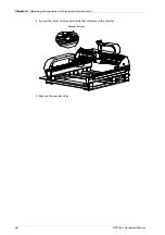
5. Loosen the two screws as shown in Figure 92.
Figure 92.
Encoder carrier screws
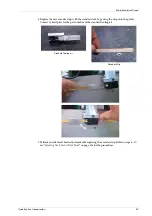
6. Insert a RENISHAW 0.8 mm spacer between the read head and the scale. Contact
CyberOptics for the part number of the REINSHAW spacer.
7. Slightly press the read head with finger to clamp the spacer and tighten the screws.
8. Move the carrier aside slowly and remove the spacer.
i
Note:
The required 0.8 mm air gap must be maintained in order for the encoder to deliver
accurate position feedback and to enable the stage to position accurately.
Screw
Screw
REINSHAW
0.8mm Spacer
Caution:
Do not scratch the scale.
Summary of Contents for SE500CP
Page 1: ...SE500CP Hardware Manual ...
Page 6: ...Contents vi SE500CP Hardware Manual ...
Page 10: ...x SE500CP Hardware Manual ...
Page 170: ...Index 160 SE500CP Hardware Manual ...


