


INSTALLING YOUR UPS SYSTEM
- continued
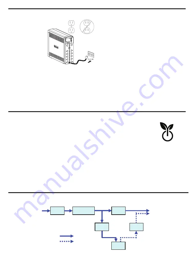
3. Plug the UPS
into a 2 pole, 3
wire grounded
receptacle (wall
outlet). Make
sure the wall
branch outlet
is protected
by a fuse or
circuit breaker
and does not
service equipment with large electrical
demands (e.g. air conditioner, refrigerator,
copier, etc.). The warranty prohibits the use
of extension cords, outlet strips, and surge
strips in conjunction with the UPS unit.
4. Press the power switch to turn the unit on.
The Power On indicator light will illuminate
and the unit will “beep”.
5. If an overload is detected, an audible alarm
will sound and the unit will emit one long
beep. To correct this, turn the UPS off and
unplug at least one piece of equipment
from the battery power supplied outlets.
Make sure the circuit breaker is depressed
and then turn the UPS on.
6. To maintain optimal battery charge, leave
the UPS plugged into an AC outlet at all
times.
7. To store the UPS for an extended period
of time, cover it and store with the battery
fully charged. While in storage, recharge
the battery every three months to ensure
optimal battery life.
8. Ensure the wall outlet and UPS are located
near the equipment being attached for
proper accessibility.
SYSTEM FUNCTION BLOCK DIAGRAM
EMI
Filter
Surge
Suppressor
AVR
Charger
AC/DC
Battery
Inverter
Input
Output
Normal Mode
Battery Mode
Advanced Energy-Saving Patented Bypass Technology
CyberPower’s patented GreenPower UPS™ with Bypass Technology reduces UPS
energy costs by up to 75% compared to conventional UPS models. Even when utility
power is normal, conventional UPS models constantly pass power through a transform-
er. By contrast, under normal conditions the advanced circuitry of a GreenPower UPS™
bypasses the transformer. As a result, the power efficiency is significantly increased
while decreasing waste heat, using less energy, and reducing energy costs. When an
abnormal power condition occurs, the GreenPower UPS™ automatically runs power
through its transformer to regulate voltage and provide “safe” power. Since utility power is normal over 88% of
the time, the GreenPower UPS™ operates primarily in its efficient bypass mode. The GreenPower UPS™ is also
manufactured in accordance with the Restriction on Hazardous Substances (RoHS) directive making it one of
the most environmentally-friendly on the market today.
CYBERPOWER GREENPOWER UPS™ TECHNOLOGY
G
REEN
P
OWER
UPS
™
Energy-Saving Technology


