background image

CPS1100AVR  

Guaranteed Uninterruptible Power System


5

. Turn the UPS off and unplug it. 

6. 

Connect the serial interface cable 

to serial port

 on the UPS and an open serial port on the back of the computer.   

(Note: You must use the serial cable that was supplied with the unit). 

7. Plug the UPS into an AC outlet, turn the UPS on and start your computer. 
8. Windows will find new hardware. 
9. Insert the PowerPanel Plus™ disk into the floppy drive. 
10. Follow the on-screen instructions. 
11. When the installation is completed, remove the floppy disk. 
 

When

 the installation is completed

, the PowerPanel Plus™ software will appear on your screen for a few seconds, and 

then minimize.    It will appear as a blue and white battery icon located in the system tray, near the clock. 


Operating Instructions 

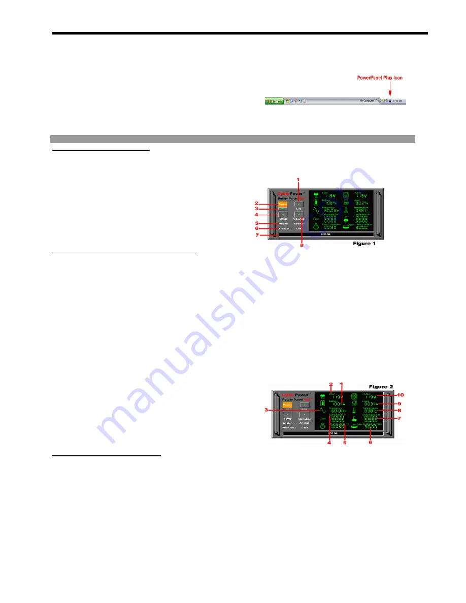
PowerPanel Plus™ Main Menu


(See Figure 1 ) 

1. Log:

  Click on the log button to open the 

Log 

Window

2. Power:

    Click on the power button will exit the 

software window. 

3. Minimize 

Button: 


Click this button to minimize the 

software. 

4. Setup:

    Click the setup button to open the 

Setup 

Window

5. Model:

    This shows the model of the CyberPower 

UPS that is being used. 

6. Version: 


This shows the 

hardware version

7. Status 

Bar: 


The area display messages about the 

status of the software. 

8. Schedule:

    Click this button to open the 

Schedule 

Window


PowerPanel Plus™ Main Window Description    (See Figure 2 )


1. Battery Level:  

This indicator displays the current 

charge on the battery.  The indicator will display a      
red color when a power failure occurs.   

2. Input Voltage:   

This reading shows the current input 

voltage of the utility power.    The input normally 
appears in green, but will turn red if the input voltage is 
not operating normally.


3. Frequency:

  This indicator displays the frequency of 

the utility power. 

4.

.

Scheduled On:

    PowerPanel Plus™ can be scheduled 

to turn your computer system on. This indicator 
displays scheduled on settings that will occur in the 
next seven days. 

5. Final Countdown:

  When PowerPanel Plus™ detects 

that the utility voltage is not operating normally, the final 
countdown will begin.  When the countdown reaches 
zero, PowerPanel Plus™ will save and close any open 
files, and then shut down the operating system in an 
intelligent and orderly manner. 

6. Approximate Backup Time:

    This indicator shows the 

approximate amount of backup time that is available, 
based    upon the battery capacity and the load on the 
system.  This indicator can appear in red, yellow, or 

green, depending upon the number of minutes 
available. 

7.  Scheduled Off:

    PowerPanel Plus™ can be set to 

automatically shutdown the computer system at a user 
specified time scheduled off settings that are set to 
occur within seven days will be displayed. 

8.  Temperature:

    This indicator displays the internal 

operating temperature of the unit.    If the temperature 
exceeds 158°F (70°C), the indicator will change from 
green to red. 

9.  Load Level:

    This indicator shows the % of capacity 

of the battery outlets that is currently being             
used.    This indicator    appears in green or gray, but 
will turn red if the load exceed 90%. 

10. Output  Voltage:

  This indicator shows the   output 

voltage of the UPS. 


PowerPanel Plus™ Setup Window    (See Figure 3 ) 
1.  UPS is Installed On:

    This shows the current port 

that the UPS is using.    The port assigned to the 
UPS needs to be used exclusively for the 
PowerPanel™ software. 

2. Buzzer 

On: 


This toggles the audible alarm on and 

off.. 

3. Play 

Sound: 


Voice is being played when the UPS 

is turning on or facing a power outage. 

4.  Time between Power Failure and Shutdown:


This is the user controllable delay between when the 
power fails and the software starts the shutdown 
process.    If unchecked, the unit will run on battery 
until the low battery signal is received (2 minutes of 
backup time remaining) and then start the shutdown 
process. 

5.  Time between Power Failure and Initial Warning:


This setting determines the delay between when the 
power fails and the first audible alarm.


6.  Delay between Warning Messages:

  User 

adjustable setting for the delay between the audible 
alarms that occur during a power failure. 

7. UPS 

Self-Test:

    Allows the user to test the UPS 

without having to unplug the unit from the wall.   
When 

Run 

is clicked, the


unit will switch to battery 

power and the unit will beep. 

5

Summary of Contents for CPS1100AVR

Page 1: ...User Manual for CPS1100AVR with USB Serial Interface and PowerPanel Plus Software ADDITIONAL INSTALLATION TIPS CAN BE FOUND AT www cyberpowersystems com faqs htm ...

Page 2: ...ot remove the cover secured by star shaped screws No user serviceable parts are inside except for the battery Refer servicing to qualified personnel CAUTION The battery can energize hazardous live parts inside even when the AC input power is disconnected CAUTION UPS must be connected to an AC power outlet with fuse or circuit breaker protection Do not plug into an outlet that is not grounded If yo...

Page 3: ...trical equipment from the outlet and have an electrician check the outlet to insure proper wiring 8 AVR Indicator This LED indicates that the UPS is operating in automatic voltage regulation mode 9 Using Battery Indicator This illuminates during a utility failure indicating that the battery is supplying power to the battery power supplied outlets 10 Check Battery This illuminates indicating a weak...

Page 4: ...cords If used the extension cord must be rated for 15 amps DO NOT plug an extension cord surge suppressor or other multiple outlet device into the battery supplied outlets of the product This will cause an overload and will also VOID the warranty 6 Depress the power switch to turn the unit on The power on indicator light will illuminate 7 If an overload is detected an audible alarm will sound and ...

Page 5: ... instructions 6 When the installation is completed remove the floppy disk For Windows NT 1 Click on Start point to Settings and then click Control Panel 2 Double click on the UPS Icon 3 Remove the check mark from the box labeled UPS is installed on and Click OK 4 Acknowledge the message that the UPS is in an unknown state 5 Exit to the desktop then shutdown your computer 6 Turn the UPS off and unp...

Page 6: ...erating normally the final countdown will begin When the countdown reaches zero PowerPanel Plus will save and close any open files and then shut down the operating system in an intelligent and orderly manner 6 Approximate Backup Time This indicator shows the approximate amount of backup time that is available based upon the battery capacity and the load on the system This indicator can appear in r...

Page 7: ...ups and shutdowns 3 Turn On Select the day date and time that you want the computer system to restart Can only be used in conjunction with a scheduled shutdown 4 Delete Delete the selected item from the schedule 5 Add Adds an item to the schedule 6 Cancel This button is used to exit the log window without saving any changes 7 OK This button is used to exit the shutdown window and save any changes ...

Page 8: ...he operating system 6 Once the computer system is shutdown turn the UPS off As the battery discharges the unit will beep more rapidly indicating that the battery is nearing discharge Once the test is complete plug the UPS back in to the AC outlet and start your computer Please allow 4 hours for the UPS to recharge before attempting another self test REPLACING THE BATTERY Contact your dealer or cal...

Page 9: ...tery wires from the battery 8 Install the replacement battery by connecting the red wire to the positive terminal of the battery and connecting the black wire to the negative terminal of the battery 9 Slide the battery back into the compartment 10 Replace the outlet cover and the 6 retaining screws 11 Recharge the unit for 4 8 hours to ensure the UPS performs expected runtime REMINDER Batteries ar...

Page 10: ... On Off Up Long Beep Overload OccursintheBattery power SuppliedOutlets TurntheUPSoffand unplugatleastonepieceofequipmentfrom theUPS Wait5seconds resetthecircuit breakerandturntheUPSon On On Off On Fla sh Off Off On Set None WeakBattery Rechargethebatteryforat least8hours IfCheckBatteryisilluminated contactCyberPowerSystemsforbattery replacementinformation Off Off Off Off Off Set Off SurgeProtectio...

Page 11: ...tional serial port Move the cable to this port The unit is not providing battery power Shutdown your computer and turn the UPS off Wait 10 seconds and turn the UPS back on This should reset the unit PowerPanel Plus is inactive all icons are gray The serial cable is not the cable that was provided with the unit You must use the cable that was included with the unit for the software and the unit to ...

Page 12: ...and therefore entitled coverage under the Limited Warranty and the Power Control Guarantee Registration is not required for Limited Warranty coverage but note if you do not complete a registration card you will be required to provide proof of purchase as described below to have the benefits of this Limited Warranty LIMITED WARRANTY CyberPower warrants to you the Initial Purchaser that the Product ...

Page 13: ... tech cyberpowersystems com within ten 10 days of the event for which you want to make a claim for warranty service 3 When you call write or E Mail identify the Product the Purchase Date and the item s of Connected Equipment Have information on all applicable insurance or other resources of recovery payment that are available to the Initial Customer for the Connected Equipment and the name of the ...

Page 14: ... transmission 3 Damage from any circumstance described as excluded above with respect to the Product 4 Damages from fire flood wind rain rising water or leakage or breakage of plumbing from abuse misuse or alteration of either the Product or the Connected Equipment Exclusion of Consequential and Other Damages The sole and exclusive remedies of the Initial Customer are those provided by the Limited...

Page 15: ...to an outlet on a circuit different from that to which the receiver is connected 4 Consult the dealer or an experienced radio TV technician for help Any special accessories needed for compliance must be specified in the instruction CAUTION A shielded type power cord is required in order to meet FCC emission limits and also to prevent interference to the nearby radio and television reception It is ...

Reviews: