background image

 CPS525SL / CPS725SL 

Guaranteed Uninterruptible Power System 


IMPORTANT SAFETY INSTRUCTIONS (SAVE THESE INSTRUCTIONS)


This manual contains important safety 
instructions.  Please read and follow all 
instructions carefully during installation and 
operation of unit.  Read this manual thoroughly 
before attempting to unpack, install, or operate. 

CAUTION!


To prevent the risk of fire or electric 

shock, install in a temperature and humidity 
controlled indoor area, free of conductive 
contaminants.  (Please see specifications for 
acceptable temperature and humidity range). 

CAUTION!


To reduce the risk of electric shock, 

do not remove the cover except to service the 
battery.  No user serviceable parts inside except 
for battery. 

CAUTION!


Hazardous live parts inside can be 

energized by the battery even when the AC input 
power is disconnected. 

CAUTION!


UPS must be connected to an AC 

power outlet with fuse or circuit breaker 
protection.  Do not plug into an outlet that is not 

grounded.  If you need to de-energize this 
equipment, turn off and unplug the unit. 

CAUTION!


To avoid electrical shock, turn off the 

unit and unplug it from the AC power source 
before servicing the battery or installing a 
computer component. 

DO NOT USE FOR MEDICAL OR LIFE 
SUPPORT EQUIPMENT!


CyberPower Systems 

does not sell products for life support or medical 
applications.  

DO NOT

 use in any circumstance 

that would affect operation or safety of any life 
support equipment or with any medical 
applications or patient care. 

DO NOT USE WITH OR NEAR AQUARIUMS!


To reduce the risk of fire or electric shock, do not 
use with or near an aquarium.


Condensation 

from the aquarium can cause the unit to shor

out. 

 
DESCRIPTION 


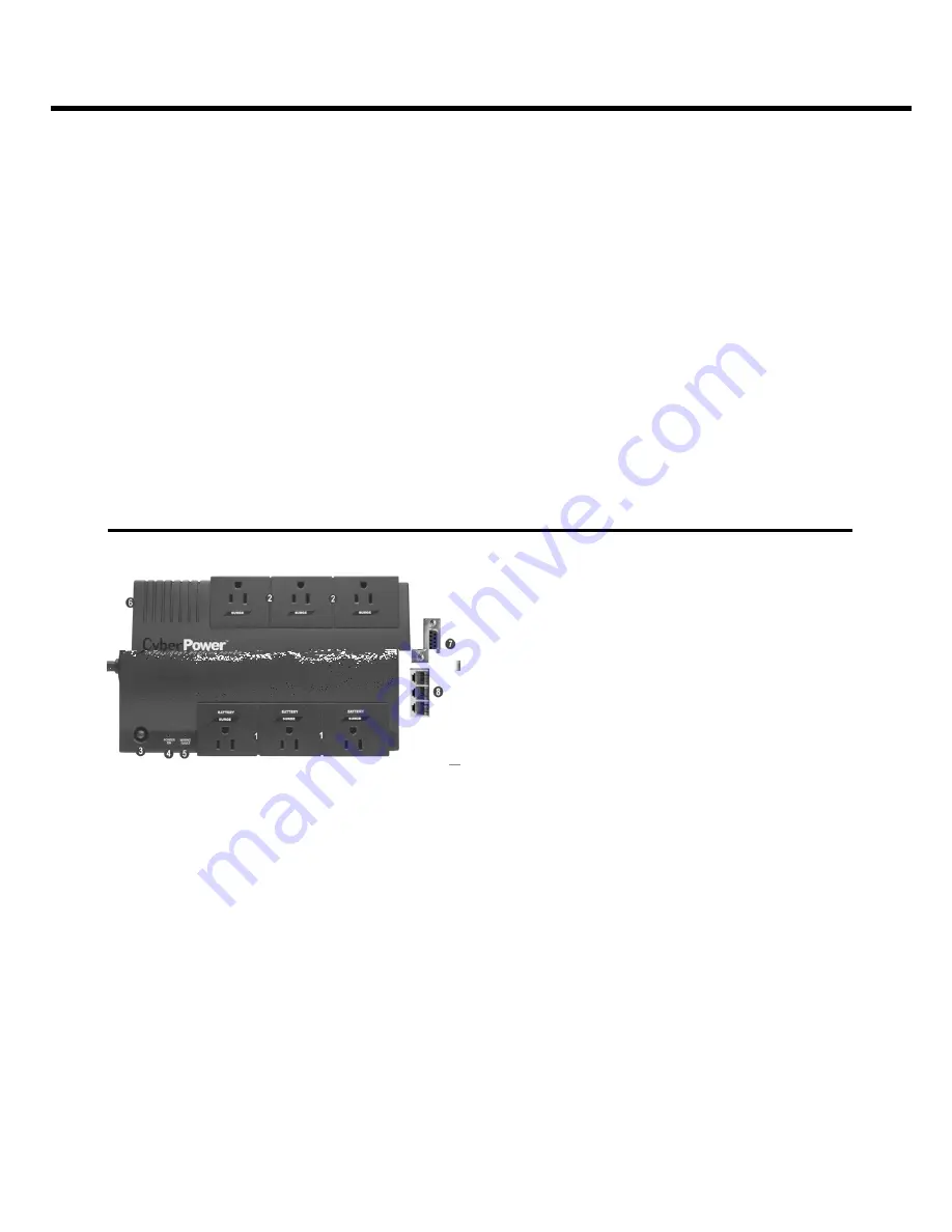
Battery/Surge Outlets 

Provides three battery powered/surge outlets for 
connected equipment and insures temporary 
uninterrupted operation of your equipment during 
a power failure. 


Full-Time Surge Protection Outlets 

Provides three always on surge suppression 
outlets. 


Power Switch 

Can be used as a mater on/off switch for 
equipment connected to the battery power 
supplied outlets. 


Power On Indicator 

This LED is illuminated when the utility condition 
is normal and the UPS outlets are providing 
power, free of surges and spikes. 


Electrical Wiring Fault Indicator 

This LED indicator will illuminate to warn the user 
that a wiring problem exists, such as bad ground, 
miss ground or reversed wiring.  If this is 
illuminated, user is advised to disconnect all 
electrical equipment from the outlet and have an 
electrician check to ensure the outlet is properly 
wired. 


Circuit Breaker 

Located on the side of the UPS, the circuit 
breaker serves to provide overload and fault 
protection.  Under normal operating conditions, 
the circuit breaker is depressed. 


Serial Port to PC 

This port allows connection and communication 
from the DB-9 serial port on the computer to the 
UPS unit.  The UPS communicates its status to 
the PowerPanel™ software.  This interface is also 
compatible with the UPS service provided by 
Windows NT and Windows 2000. 


Communication Protection Ports 

Communication protection ports will protect any 
standard modem, fax or telephone line.


Outlets Designed for AC Adapters 

Allows six AC power adapter blocks to be 
plugged into the UPS without blocking adjacent 
outlets. 

Summary of Contents for CPS525SL

Page 1: ...CPS525SL CPS725SL Guaranteed Uninterruptible Power System 1 User Manual for CPS525SL CPS725SL with USB Interface and PowerPanel Software ADDITIONAL INSTALLATION TIPS CAN BE FOUND AT ...

Page 2: ...ctions completely This UPS is designed to provide guaranteed power protection for connected electronic equipment The accompanying PowerPanel software saves data closes open applications and automatically shuts down your computer system in an intelligent and orderly manner Safety Instructions 1 Description 1 Determining Power Requirements 2 Hardware Installation Guide 2 Software Installation Guide ...

Page 3: ...uce the risk of fire or electric shock do not use with or near an aquarium Condensation from the aquarium can cause the unit to short out DESCRIPTION Battery Surge Outlets Provides three battery powered surge outlets for connected equipment and insures temporary uninterrupted operation of your equipment during a power failure Full Time Surge Protection Outlets Provides three always on surge suppre...

Page 4: ...equirements There are many factors that can effect the amount of power that your computer system will require The total load that you will be placing on the battery powered outlets should not exceed 80 of the unit s capacity Hardware Installation Guide 1 Your new UPS may be used immediately upon receipt However recharging the battery for at least four hours is recommended to insure that the batter...

Page 5: ...PANEL SOFTWARE INSTALLATION GUIDE Note Use of the software is optional The UPS will provide surge suppression and battery backup without the software You must use the software if you wish to have the automatic shutdown feature Software Installation Optional Cyber Power UPS can provide surge suppression and battery backup without the software However if you need to schedule for UPS Auto shutdown th...

Page 6: ...k and restart your computer When your computer restarts the PowerPanel software will appear on your screen for a few seconds and then minimize It will appear as a blue and white battery icon located in the system tray near the clock FOR WINDOWS 2000 1 Click on Start point to Settings and then click Control Panel 2 Double click on Power Options 3 On the UPS Tab click Select 4 In the UPS Selection D...

Page 7: ... can be downloaded from www cyberpowersystems com downloads htm It works in conjunction with the UPS to provide full protection of valuable computer systems applications and data In the event of a power failure PowerPanel automatically saves and closes open files under auto assigned file names or existing files names after a software controlled delay The computer 8 put 8o err 8 pu auso 5 7 m 1illy...

Page 8: ... an item to the schedule 6 Clear Button This button is used to delete the selected item 7 Cancel Shutdown This button is used to cancel the current shutdown 8 Day Date and Time This is the area where you select the day date and time that you want the shutdown to occur Once you have selected it click the Add Button to add the item to the schedule Please note The use of the schedule is optional and ...

Page 9: ...then save the file to the PCTemp folder which is located in the root directory of your C drive where C is the name of your main hard drive Once all open files have been saved and closed PowerPanel will shutdown the operating system Once the operating system is shutdown the UPS will turn off within 90 seconds Wait until the UPS has turned off before plugging the UPS back into the outlet Once the te...

Page 10: ...ing the red wire to the positive terminal of the battery and connecting the black wire to the negative terminal of the battery 9 Slide the battery back into the compartment 10 Replace the outlet cover and the 6 retaining screws 11 Recharge the unit for 4 8 hours to ensure the UPS performs expected runtime REMINDER Batteries are consider HAZARDOUS WASTE and must be disposed of properly Contact your...

Page 11: ...it on On Off On Set None Electrical Wiring Fault This indicates a wiring problem with the AC outlet such as bad ground miss ground or reversed wiring User is advised to disconnect all electrical equipment from the outlet and have an electrician check the outlet to insure proper wiring ...

Page 12: ...cted to an AC outlet The unit must be connected to a 110 120v 60Hz outlet The battery is worn out Contact CyberPower Systems about replacement batteries at tech cyberpowersystems com The UPS will not turn on Mechanical problem Contact CyberPower Systems at tech cyberpowersystems com The serial cable is not connected Connect the serial cable to the UPS unit and an open serial port on the back of th...

Page 13: ...CPS525SL CPS725SL Guaranteed Uninterruptible Power System 11 Additional troubleshooting information can be found at www cyberpowersystems com FAQs htm ...

Page 14: ...0 C to 35 C Operating Relative Humidity 0 to 95 NON CONDENSING Size Length x Width x Height 9 7 8 x 6 3 16 x 3 1 8 25 8cm x 15 9cm x 8 3cm Net Weight 13 lbs 15 lbs Typical Battery Recharge Time 8 hours typical from total discharge Typical Battery Life 3 to 6 years depending on number of discharge recharge cycles Battery Type 12V 7 0AH 12V 9 0AH Recommended Battery Spill proof Maintenance free seal...

Page 15: ... as described below to have the benefits of this Limited Warranty Limited Warranty CyberPower warrants to you the Initial Purchaser that the Product will be free from defects in material and workmanship for three years from the date of original purchase subject to the terms of this Limited Warranty To be covered you must still be the owner of the Product at the time of the failure that results in ...

Page 16: ...CPS525SL CPS725SL Guaranteed Uninterruptible Power System 14 or not the Initial Customer makes a claim for recovery including but not limited to a ...

Page 17: ...s of the event for which you want to make a claim for warranty service 3 When you call write or E Mail identify the Product the Purchase Date and the item s of Connected Equipment Have information on all applicable insurance or other resources of recovery payment that are available to the Initial Customer for the Connected Equipment and the name of the power utility supplier for the location of th...

Page 18: ...unded and code compliant 120 volt power lines in the United States and Canada transients surges or spikes on standard telephone land lines PBX telephone equipment lines or Base 10 100T Ethernet lines when properly installed and connected This exclusion applies for example to fluctuations in data transmission or reception by CATV or RF transmission or fluctuations or by transients in such transmiss...

Page 19: ...limits for a Class B Digital Device pursuant to Part 15 of the FCC Rules These limits are designed to provide reasonable protection against harmful interference in residential installation This equipment generates uses and can radiate radio frequency energy and if not installed and used in accordance with the instructions may cause harmful interference to radio communications However there is no g...

Reviews: