17
HSTP3T 15/20KE-C/KEBC-C User Manual
Chapter 2 Installation Instruction
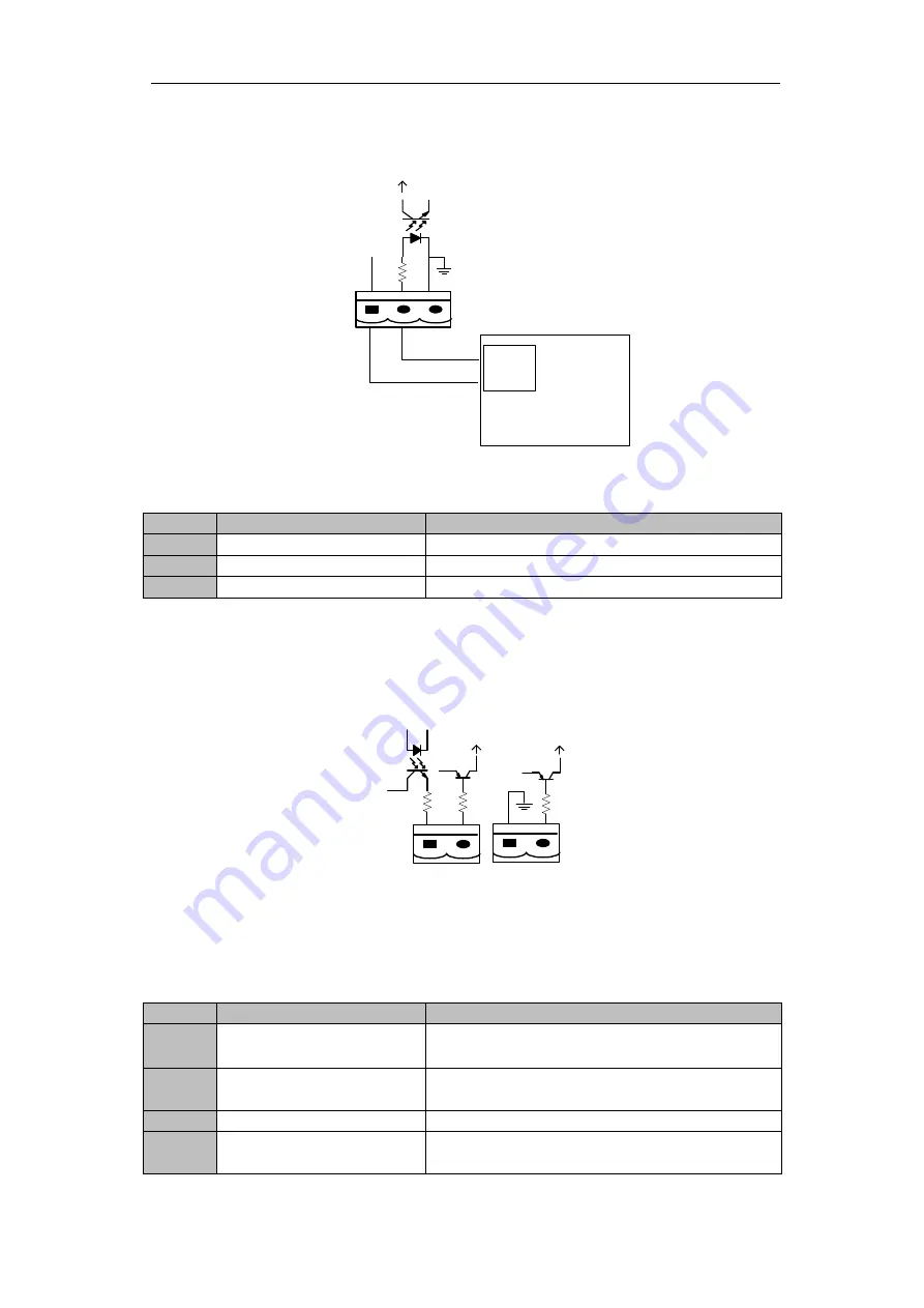
The default function of J5 is the interface for generator J5 Connect pin 2 of J5 with +24V
power supply; it indicates that the generator has been connected with the system. The
interface diagram is shown in Fig.2-13, and interface description is shown in Table 2.8.
J5
GEN
+24V
AUX-N.O.
AUX-N.O.
Generator
Fig.2-13 Diagram of status interface and connection of generator
Table 2.8 Description of status interface and connection of generator
Port
Name
Function
J5-1
+24V_DRY
+24V
J5-2
GEN_CONNECTED
Connection status of generator
J5-3
GND_DRY
Power ground for +24V
BCB Input Port
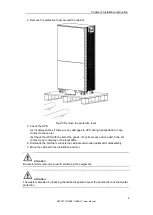
The default function of J6 and J7 are the ports of BCB. The port diagram is shown in
Fig.2-14, and description is shown in Table 2.9.
B
C
B
_
D
R
V
B
C
B
_
C
O
N
T
J6
J7
B
C
B
_
O
N
L
+24V
+24V
+24V
Fig.2-14 BCB Port
Table 2.9 Description of BCB port
Port
Name
Function
J6-1
BCB_DRIV
BCB contact drive, pr24V voltage
,
20mA
drive signal
J6-2
BCB_Status
BCB contact status, connect with the normally
open signal of BCB
J7-1
GND_DRY
Power ground for +24V
J7-2
BCB_Online
BCB on-line input (normally open) , BCB is
on-line when the signal is connecting with J7-1
Summary of Contents for HSTP3T15KE-C
Page 2: ...Ver 1 0 0 ...


