Chapter 4 Operations
34
HSTP3T 15/20KE-C/KEBC-C User Manual
4.5 Installation of Parallel Operation System
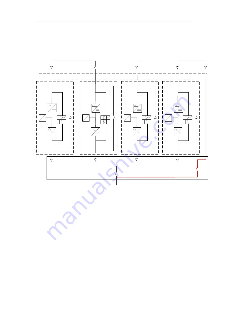
4.5.1 Parallel system diagram
Up to four UPS could be paralleled
,
with a diagram as shown in Fig.4-6.
UPS1
Load Connected
Output Power Supply
Power Supply
UPS2
UPS3
UPS4
Fig. 4-6 Parallel diagram
The parallel board is located at the back of the UPS cabinet, as is shown in Fig.4-7.
Summary of Contents for HSTP3T15KE-C
Page 2: ...Ver 1 0 0 ...


