Chapter 3 LCD Panel
22
HSTP3T 15/20KE-C/KEBC-C User Manual
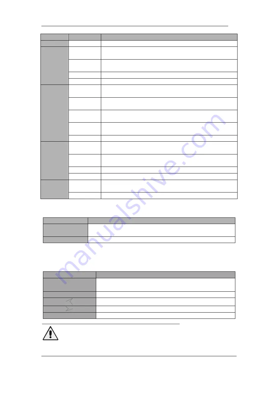
Indicators
State
Description
Off
Battery and battery converter normal, battery not charging
Bypass
indicator
Steady
green
Load supplied by bypass
Steady red
Bypass abnormal or out of normal range, or static bypass
switch fault
Flashing red
Bypass voltage abnormal
Off
Bypass normal
Inverter
indicator
Steady
green
Load supplied by inverter
Flashing
green
Inverter on, start, synchronization or standby (ECO mode) for at
least one module
Steady red
System output not supplied by inverter, inverter fault for at least
one module.
Flashing red
System output supplied by inverter, inverter fault for at least one
module.
Off
Inverter not operating
Load
indicator
Steady
green
UPS output ON and normal
Steady red
UPS overload time is out, or output short, or output no power
supply
Flashing red
Overload output of UPS
Off
No output of UPS
Status
indicator
Steady
green
Normal operation
Steady red
Failure
There are two different types of audible alarm during UPS operation, as shown in Table 3.2.
Table 3.2 Description of audible alarm
Alarm
Description
Two short alarm
with a long one
When system has general alarm (for example: AC fault),
Continuous alarm
When system has serious faults (for example: fuse or hardware fault)
3.2.2 Control and Operation Keys
Control and operation keys include four keys. The functions description is shown in Table
3.3.
Table 3.3 Functions of Control and operation keys
Function Key
Description
EPO
Long press
,
cut off the load power (shut down the rectifier,
inverter, static bypass and battery)
HOME
Back to home page
Page up
Page down
ENTER
Confirm
Attention
When bypass frequency is over track, there is interruption time(less than 10ms) for transferring
from bypass to inverter.
Summary of Contents for HSTP3T15KE-C
Page 2: ...Ver 1 0 0 ...


