background image

 26 


6.2. Converter Function 

Brief introduction of Converter function

˖

˖


In converter mode, the UPS would free run with fixed output frequency (50Hz or 
60Hz). Once the mains power is loss or abnormal, the UPS would transfer to Battery 
mode and the load is supplied continuously.   
The great virtue is the output frequency is fixed, which is required by some very 
sensitive loads.   

Set the function

˖


The function could be enabled through the LCD setting in Bypass mode. Enter the 
power strategy setting menu by following chapter of 5.3. 

6.3. Parallel Function 

Brief introduction of the redundancy

˖


N+X is currently the most reliable power supply structure. N represents the minimum 
UPS number that the total load needs, X represents the redundant UPS number, i.e. 
the fault UPS number that the system can handle simultaneously. When the X is 
larger, the reliability of the power system is higher. For occasions where reliability is 
highly depended on, N+X is the optimal mode. 
As long as the UPS is equipped with parallel cables, up to 4 UPS can be connected in 
parallel to realize output power sharing and power redundancy. 

How to install a new parallel UPS system

˖


1)  Before installing a new parallel UPS system, user need to prepare input and 

output wires, input and output breaker, main maintenance bypass switch. 

2)  Remove the cover plate of the parallel port on the UPS, connect each UPS one 

by one with the parallel cable, and re-screw the Parallel port cover which is 
supplied in the accessories. See Fig.6-1. 

3)  Strictly follow the chapter of 4.4, the wiring requirement of single UPS to perform 

the wiring of each UPS. 

4)  Connect the output wires of each UPS to an output breaker panel. 
5) 

Disconnect the Jumper on J1 and J2 first

, and connect each output breaker to 

a Parallel output breaker and then to the loads. 

6)  Each UPS needs an independent battery pack. 

7)  Please refer to the wiring diagram in the following diagram. See Fig.6-2, Fig.6-3. 


Summary of Contents for OLS3S15KE

Page 1: ...Userɉ ɉs Manual OLS3S15KE XL OLS3S20KE XL CyberPower Systems Inc www cyberpower com K01 C000121 02 ...

Page 2: ...lectrical Installation 11 4 5 Internal Battery Pack Connecting Procedure of OLS3S15KE 20KE 14 4 6 External Battery Pack Connecting Procedure 15 4 7 EPO Connection 16 4 8 Backfeed Protection 16 5 Operation 17 5 1 Display Panel 17 5 2 Turning On and Turning Off UPS 19 5 3 LCD Operation 20 6 Special Function 25 6 1 ECO Function 25 6 2 Converter Function 26 6 3 Parallel Function 26 7 Trouble Shooting ...

Page 3: ...ance 34 8 1 Replacement and Disposal of Batteries 34 8 2 Easy for Battery Replacement 35 9 Communication Port 37 9 1 USB Interface 37 9 2 Dry contact Interface optional 37 9 3 RS232 Interface 37 9 4 Intelligent slot 37 ...

Page 4: ...rnal UPS battery cabinets z An integral single emergency switching device which prevents further supply to the load by the UPS in any mode of operation should be provided in the building wiring installation z An appropriate disconnect device as short circuit backup protection should be provided in the building wiring installation z For three phase equipment connection to an IT power system a four ...

Page 5: ...ltage exists in the capacitor or BUS capacitor terminals z Batteries must be replaced only by qualified personnel z Caution risk of electric shock The battery circuit is not isolated from the input voltage Hazardous voltages may occur between the battery terminals and the ground Verify that no voltage is present before servicing z Batteries have a high short circuit current and pose a risk of shoc...

Page 6: ...onducted Emission IEC EN 62040 2 Category C3 Radiated Emission IEC EN 62040 2 Category C3 EMS ESD IEC EN 61000 4 2 Level 3 RS IEC EN 61000 4 3 Level 3 EFT IEC EN 61000 4 4 Level 4 SURGE IEC EN 61000 4 5 Level 4 Low Frequency Signals IEC EN 61000 2 2 Warning This is a product for commercial and industrial application in the second environment installation restrictions or additional measures may be ...

Page 7: ...irect current This direct current powers the inverter On the basis of this DC voltage the inverter generates a pure sinusoidal AC voltage which is constantly powering the loads Computers and Peripherals are thus powered entirely by the UPS In the event of power failure the maintenance free batteries power the inverter This manual covers the UPS listed as follows Please confirm whether it is the mo...

Page 8: ...viding outstanding performance and reliability the UPS s unique benefits include z True online double conversion technology with high power density utility frequency independence and generator compatibility z True three phase power factor correction and high input power factor PF 0 99 Save the installation cost and reduce the pollution back feed into upstream power system z Online UPS design with ...

Page 9: ...ndancy to increase the reliability and flexibility The max parallel number is 4 z User friendly LCD display and LED indicators z Easily battery exchange or extension and available to extend the backup time 3 2 Product Specification and Performance General Specification Model OLS3S15KE XL OLS3S20KE XL Power Rating 15kVA 13 5kW 20kVA 18kW Input Voltage Range 110 276Vac Depends on load level Rated Cu...

Page 10: ...hronized 50 60Hzf10 Line mode f0 1 of normal frequency Battery mode THDV THD 2 Full load Linear Load THD 5 for reference non linear load Overload Line model 5 minutes 100 110 1 minute 110 130 10 seconds 130 150 2 seconds 150 Battery model 1 minutes 100 110 10 seconds 110 130 2 seconds 130 The overload capacity would be derated automatically while the circumstance temperature is larger than 35 degr...

Page 11: ... 0ȭ 40ȭ 95 1000m 15ȭ 50ȭ Note if the UPS is installed or used in a place where the altitude is above than 1000m the output power must be derated in use please refer to the following Altitude M 1000 1500 2000 2500 3000 3500 4000 4500 5000 Maximum Power 100 95 91 86 82 78 74 70 67 ...

Page 12: ...9 4 Installation 4 1 Tools Tools Kit Lifter Phillips screwdriver Scissors Wrench 4 2 Unpacking Unpacking step1 Unpacking step2 Unpacking step3 Unpacking step4 ...

Page 13: ...tware Section for free download CAUTION Inspect the appearance of the UPS to see if there is any damage during transportation Do not turn on the unit and notify the carrier and dealer immediately if there is any damage or lacking of some parts User s Manual UPS Parallel Cable USB Cable RS232 Cable optional Parallel Cable Terminal ...

Page 14: ...ation is completed the side mounting brackets used in shipping shall be fixed back to ensure the stability of the UPS enclosure If impossible additional stability can be added by anchoring the mounting brackets to the floor with M8 bolts See Fig 4 1 Fig 4 1 Additional stability 4 4 2 Power Wires Installation Installation and wiring must be performed in accordance with the local electric code and t...

Page 15: ...rnal Battery Cabinet Positive Pole Negative pole Min conductor cross section Max conductor cross section 21mm 25mm Line input Backfeed protection device A 4 pole disconnection device with 100A 250Vac less than 15s break time and min 1 4mm clearance will be used in final installation for backfeed protection in line input Main2 input Backfeed protection device A 2 pole disconnection device with 100A...

Page 16: ...ch consumes electric equipment and the ground wire The wire diameter of protective earth ground wire should be at least as above mentioned for each model and green wire or green wire with yellow ribbon wire is used 5 After having completed the installation make sure the wiring is correct 6 Please install the output breaker between the output terminal and the load and the breaker should with leakag...

Page 17: ...up time may be less than the standard value 10 If it is necessary to connect the inductance load such as a monitor or a laser printer to the UPS the start up power should be used for calculating the capacity of UPS as its start up power consumption is too big when it is started 4 5 Internal Battery Pack Connecting Procedure of OLS3S15KE 20KE 1 Loosen the screws to remove the front panel and discon...

Page 18: ...OLS3S20KE has internal battery pack first of all disconnect the internal battery pack DC connectors Please refer to the chapter 4 5 z A DC breaker must be connected between the external battery pack and the UPS The capacity of breaker must be not less than the data specified in the general specification z Set the external battery pack breaker in OFF position and connect the batteries z Connect the...

Page 19: ...d enter LCD menu illustrated in the chapter of 5 3 to clear EPO status then UPS would stop alarm and recover to Bypass model And UPS needs be turned on by manual operation 4 8 Backfeed Protection On customers side an additional external isolation device magnetic contactor MC or minimum voltage tripping device must be provided as shown in the following diagram The isolation device must be able to c...

Page 20: ... the unit is no power and has connected with battery press this button more than 200ms to power on Turn on When the unit is powered on and is in Bypass mode press this button more than 1s to turn on Turn off When the unit has been turned on press this button more than 3s to turn off Enter Press this button more than 200ms to confirm current selection or enter the current selection window ESC Exit ...

Page 21: ...on for more than 200ms to move the focus to the down menu UPS State Normal Green LED Battery Yellow LED Bypass Yellow LED Fault Red LED Bypass mode with no output ƾ Bypass mode with output 嗟 Line mode 嗟 Battery mode 嗟 嗟 ECO mode 嗟 嗟 Battery test mode Ć Ć Ć Ć Turn on Ć Ć Ć Ć Fault mode 嗟 Warning mode ƾ UPS Condition Buzzer Status Fault active Continuous Warning active Beep every second Battery mode...

Page 22: ...se switch off the connected loads first before turning on the UPS and switch on the loads one by one after the UPS is turned on Switch off all of the connected loads before turning off the UPS Turning on UPS with mains 1 Check all the connection is correct Check the breaker of external battery pack is in ON position 2 Set input breaker in ON position At this time the fan begins to rotate LCD will ...

Page 23: ... without mains 1 To power off the UPS by pressing button continuously for more than 3s and the buzzer will beep 3s The UPS will cut off the output at once 2 A few seconds later LCD shuts down and no voltage is available from the UPS output 5 3 LCD Operation Except the default UPS status summary screen the user could get more useful information about UPS current status old events which ever occurre...

Page 24: ...e same time 3 Clear EPO status once EPO status is enabled the UPS output would be cut off To recover to normal status first EPO connector should be closed and enter this menu to clear EPO status then UPS would stop alarm and recover to Bypass model And UPS needs be turned on by manual operation 4 Single UPS off is one command to turn off one UPS which is operated currently in a parallel system and...

Page 25: ... 10 Fault 0003 12 00 00 Over tempearture 1 5 Down 200mS Up 200mS Down 200mS Up 200mS Down 200mS Up 200mS Down 200mS Up 200mS Down 200mS Up 200mS Down 200mS Up 200mS Down 200mS Up 200mS Alarm 0002 12 20 00 Line site 2 10 Enter 200mS ESC 200mS Alarm 0002 12 00 00 Overload 1 10 Up 200mS Down 200mS Fault 0003 12 00 00 Over tempearture 1 5 Enter 200mS ESC 200mS Cable loss 0003 12 00 00 Over tempearture...

Page 26: ...ults Event 0001 12 00 00 Utility abnormal 1 10 Alarm 0002 12 00 00 Overload 1 10 Fault 0003 12 00 00 Over tempearture 1 5 Clear all events Yes No Clear all faults Yes No Type model Serial number Rating Firmware version Type model OLS3S20KE Standard model Serial number Rating IP 230Vac 50Hz OP 230Vac 50Hz Power 20kVA 18kW Please input Password Firmware version Ver 0 0 1 Sub settings Fig 5 3 Main me...

Page 27: ...assword enabled disabled enabled Audio alarm enabled disabled enabled DC start enabled disabled enabled Auto Restart enabled disabled enabled Automatic overload restart enabled disabled enabled Auto Bypass enabled disabled enabled Shorted restart enabled disabled disabled Power strategy Normal ECO Converter Normal Rated output voltage 208 220 230 240V 230V Output frequency 50 60Hz 50Hz Bypass volt...

Page 28: ...the power used by the load is directly supplied from the mains power via internal filter while the utility power is in normal range so the economy mode could be gained in ECO mode Once the mains power is loss or abnormal the UPS would transfer to Line mode or Battery mode and the load is supplied continuously The great virtue is overall high efficiency 97 of UPS to save power for user But the disa...

Page 29: ... system is higher For occasions where reliability is highly depended on N X is the optimal mode As long as the UPS is equipped with parallel cables up to 4 UPS can be connected in parallel to realize output power sharing and power redundancy How to install a new parallel UPS system 1 Before installing a new parallel UPS system user need to prepare input and output wires input and output breaker ma...

Page 30: ...D TO UTILITY Main Maintenance Bypass Switch Main I P Breaker Maintenance Bypass for Parallel UPS1 O P Breaker UPS2 O P Breaker UPS3 O P Breaker Main O P Breaker UPS1 I P Breaker UPS2 I P Breaker UPS3 I P Breaker Fig 6 2 Parallel installation diagram ...

Page 31: ...l Block wiring diagram 8 The distance between the UPS in parallel and the breaker panel is required to be less than 20 meters The difference between the wires of input and output of the UPS is required to be less than 20 9 Do not switch on the output breaker of each UPS switch on the input breaker of the each UPS the UPS should work in bypass with output observe their display to check if there are...

Page 32: ...r panel of each UPS the UPS system would transfer to bypass automatically Set the own maintenance bypass switch of each UPS from UPS to BPS 4 Set the main maintenance bypass switch from UPS to BPS switch off the main output breaker and the main input breaker the UPS would shut down 5 Ensure the UPS shut down totally add the new UPS and reinstall the new UPS parallel system by following step 1 to 9...

Page 33: ... in the Line mode 7 Trouble Shooting If the UPS system does not operate correctly first check the operating information on the LCD display Please attempt to solve the problem using the table below If the problem still persists consult your dealer 7 1 Trouble Shooting According to Warning Indication Problem Displayed Possible Cause Remedy EPO active EPO connector is open Check the EPO connector sta...

Page 34: ... too high Check the ventilation of UPS and the ambient temperature Cable disconnect The parallel cable is disconnected Check the parallel cable Cable loss The parallel cable is disconnected Check the parallel cable Line differ The mains input of some UPS is disconnected Check the building wiring and input cable Check if the input breaker is closed Ensure the UPS are connected to same input source ...

Page 35: ...e loads Turn off the UPS Check if UPS output and loads is short circuit Ensure short circuit is removed before turning on again Over load Over load Check the loads and remove some non critical loads Check if some loads are failed Neg power fail The load is pure inductive and capacitive Remove some non critical loads Bypass supplies the load first ensure there is no overload then turn on UPS Over t...

Page 36: ...e Check if the input breaker is closed Emergency supply period shorter than nominal value Batteries not fully charged batteries defect Charge the batteries at least 12 hours and then check capacity Please have the following information at hand before calling the After Sales Service Department 1 Model number serial number 2 Date on which the problem occurred 3 LCD LED display information Buzzer ala...

Page 37: ... discharged every 2 months The standard charging time should be at least 12 hours z Under normal conditions the battery life lasts 3 to 5 years In case if the battery is found not in good condition earlier replacement should be made Battery replacement should be performed by qualified personnel z Replace batteries with the same number and same type of batteries z Do not replace the battery individ...

Page 38: ...tential hazardous voltages Therefore before any maintenance and repairs work is carried out switch off the breaker of the battery pack or disconnect the jumper wire of connecting between the batteries z Batteries contain hazardous voltage and current Battery maintenance such as the battery replacement must be carried out by qualified personnel who are knowledgeable about batteries No other persons...

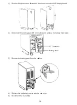
Page 39: ...tor on the LCD display board 2 Disconnect the battery pack DC connectors and remove the battery fixed plate Remove the battery pack from the cabinet 4 Replace the old battery packs with the new ones 5 Reconnect the DC cables DC Connector Battery fixed ...

Page 40: ...Intelligent slot This series is equipped with an intelligent slot for other optional card to achieve remote management of the UPS through internet intranet Please contact your local distributor for further information CyberPower Systems Inc www cyberpower com 6F No 32 Sec 1 Chenggong Rd Nangang District Taipei 115 Taiwan Entire contents copyright 2013 CyberPower Systems Inc All rights reserved Rep...

Reviews: