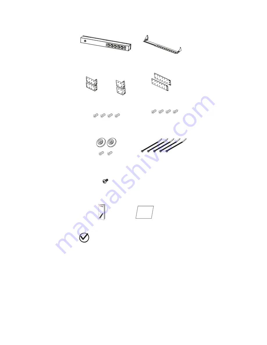
background image

Package Contents

PDU (1)

Cord Retention Tray 

(

1/2/3/4 pcs - varies by model

)

Horizontal Installation

Used (1 set)

Vertical Installation

Used (1 set)

Mounting Brackets

Vertical Mounting Brackets (1 set)

(for 0U models only) 

Keyhole Mounting Pegs (2pcs)

with Screws M4 X 6 (2pcs)

(for 0U models only)

Bracket Mounting

Screws M4 X 6 (4pcs)

Cable Tie (

12/ 15/ 21/ 24/ 30/ 36/ 45/ 

48/ 57 pcs - varies


by model

for Cord Retention Tray

Documentation:

User’s Manual

Power

Distribu

tion

Unit

User M

anual

Product Registration Card 

Product

Registration 

Card 

Check

Before using, please check to ensure the package contains all the

items shown above. If there are missing parts please contact

CyberPower technical support at www.cyberpower.com or call 

1-877-297-6937.

Safety Precautions -
Read


the


following


before


installing


or


operating 

the Power Distribution Unit (PDU):

For information on Cyberpower products, visit www.cyberpower.com

2

Cord Retention Tray 

Mounting Screws M3 X 6 

(

4/8/12/16 pcs - varies by model

Ground Screw  M5 X 6 (1 pcs)

1. 

CAUTION! 

Use ONLY the supplied hardware (including screws, pegs and 

cord retainer clips) to attach the mounting brackets. Using different 

hardware or improper installations may cause damage that is NOT covered 

by this warranty.

2. The PDU must only be plugged into a three-wire, grounded outlet on a

circuit protected by a fuse or circuit breaker. Connection to any other type

of power outlet may result in a shock hazard.

3. Do not use extension cords or adapters with this PDU.

4. Never install a PDU, or associated wiring or equipment, during a lightning

storm.

5. Check that the power cord, plug, and socket are in good condition.

6. The socket-outlet shall be installed near the equipment and shall be easily 

accessible.

7. 

CAUTION!

 To prevent the risk of fire or electric shock, this PDU


should


be

installed in a temperature and humidity controlled indoor area free of

conductive contaminants. Do not install this PDU where excessive

moisture or heat is present.

Summary of Contents for PDU10BVHVIEC16F

Page 1: ...Power Distribution Unit User s Manual...

Page 2: ...l Installation Keyhole Mounts 0U models only Cord Retention Tray installation Meter Configuration Electrical Installation Troubleshooting 6 Product Features Technical Specification 7 Basic Series 1U 2...

Page 3: ...F Metered Series 0U PDU20MVHVT20F PDU20MVHVT30F PDU20MVHVT38F PDU20MVHVIEC24F PDU20MVHVIEC30F PDU20MVHVIEC38F PDU30MVT24F PDU30MVT32F PDU30MVHVT20F PDU30MVHVT30F PDU30MVHVT38F PDU Naming Convention 1...

Page 4: ...t www cyberpower com 2 Cord Retention Tray Mounting Screws M3 X 6 4 8 12 16 pcs varies by model Ground Screw M5 X 6 1 pcs 1 CAUTION Use ONLY the supplied hardware including screws pegs and cord retain...

Page 5: ...only Step 1 Mounting bracket installation Install the screws M4 X 6 in holes diagonal from each other Step 2 PDU Mounting Install the PDU using fasteners compatible with the rack For information on C...

Page 6: ...Mounting bracket installation Attach the Vertical Mounting Brackets to the PDU with the 4 supplied Bracket Mounting Screws M4 X 6 Step 2 PDU Mounting Install the PDU using fasteners compatible with t...

Page 7: ...al and vertical installations Attach the Cord Retention Tray to the PDU with the 4 supplied Cord Retention Tray Mounting Screws M3 X 6 Tighten the Cord Retention Tray with the screw on it Use the Cabl...

Page 8: ...as outlined in the Specifications section In order to determine your total load simply add up the amperage of your devices and ensure that it does not exceed the unit s capacity Troubleshooting Probl...

Page 9: ...2Ra Input Voltage Max Current Regulatory Derated Input Current A 0 2 A 5 1 r e k a e r B t i u c r i C Plug Type NEMA L6 20P IEC 320 C20 t f 0 1 t f 0 1 h t g n e L d r o C r e w o P Output V 0 3 2 0...

Page 10: ...Name PDU30BT8F8R PDU30BT10F10R PDU30BHVT8R PDU30BHVT10R PDU30BHVT12R Input V 0 3 2 0 0 2 V 5 2 1 0 0 1 e g a t l o V Max Current Regulatory Derated Input Current 2 x A 6 1 2 x A 0 2 r e k a e r B t i...

Page 11: ...k a e r B t i u c r i C t f 0 1 h t g n e L d r o C r e w o P Output V 0 3 2 0 0 2 e g a t l o V t n e r r u C x a M Outlet Type Quantity Plug Type Indicators LED Indicators Meter Readout Physical Dim...

Page 12: ...ted Input Current Circuit Breaker Plug Type NEMA L6 20P IEC 320 C20 t f 0 1 t f 0 1 h t g n e L d r o C r e w o P Output V 0 3 2 0 0 2 V 0 3 2 0 0 2 e g a t l o V A 0 2 A 0 2 t n e r r u C x a M Outle...

Page 13: ...81x91 44 cm 1 75 x1 5 x60 4 45x3 81x152 40 cm 1 75 x1 5 x70 4 45x3 81x177 80 cm Environmental Humidity Altitude Temperature Safety Approvals Certifications Warranty 24A 30 A N A N A Lifetime Operating...

Page 14: ...Safety Approvals Certifications Warranty 16A 20 A 200 230V 16 A N A Amperage 1 75 x 1 5 x 48 4 45 x 3 81 x 121 92 cm 1 75 x 1 5 x 60 4 45 x 3 81 x 152 40 cm 1 75 x 1 5 x 70 4 45 x 3 81 x 177 80 cm Lif...

Page 15: ...30F PDU30MVHVT38F Input V 0 3 2 0 0 2 V 5 2 1 0 0 1 e g a t l o V Max Current Regulatory Derated Input Current 2 x A 6 1 2 x A 0 2 r e k a e r B t i u c r i C Plug Type NEMA L5 30P NEMA L6 30P t f 0 1...

Page 16: ...only covers the original purchaser Coverage ends if you sell or otherwise transfer the Product How Do You Get Service 1 Call us at 877 297 6937 or write to us at Cyber Power Systems USA Inc 4241 12th...

Page 17: ...ectrical code without the use of any adapters or other connectors 2 The Product must have been plugged directly into the power source and the equipment connected to the Product must be directly connec...

Page 18: ...K01 0000512 00 Cyber Power Systems Inc www cyberpower com...

Reviews: