background image

Electrical Installation

Ensure that the plug type of your PDU unit (e.g. NEMA 5-15P, NEMA 5-

20P, NEMA L5-30P) matches the wall receptacle type that you are using.

Step 1 – Receptacle evaluation

PDU must be plugged into a three-wire, grounded wall receptacle only. 

The wall receptacle must also be connected to an appropriate branch 

circuit/main with fuse or circuit breaker protection. Connection to any 

other type of wall receptacle may result in a shock hazard.

CAUTION!!

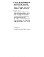
Step 2 – Plug the PDU into the wall receptacle

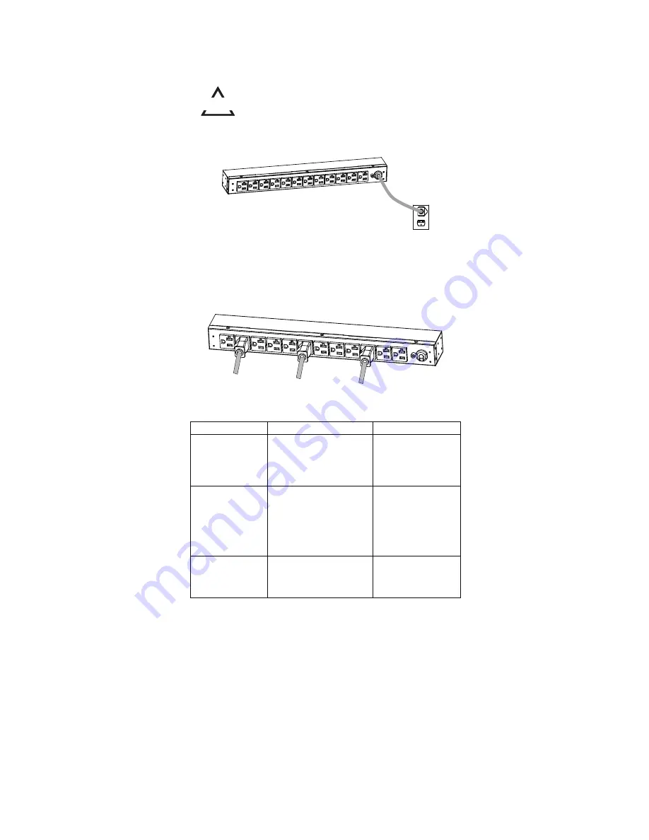
Step 3 – Attach equipment
Before attaching equipment, it is important to calculate the total load that you 

will be placing on the PDU. It is extremely important not to exceed the PDU's 

maximum current load (as outlined in the Specifications section). In order to 

determine your total load, simply add up the amperage of your devices and 

ensure that it does not exceed the unit’s capacity.

Troubleshooting

Problem

Possible Cause

Solution

PDU Outlets do not

provide power to

connected

equipment

1. Open breaker

2. Loose power cord

Reset Breaker check if

plug is completely

connected.

If the problem remains

contact tech support.

Amperage displayed

on Amperage Meter

exceeds the 

unit’s

capability (Metered

type only)

1. Overload

2. Amperage meter is

damaged

The meter will flash

when overloaded. 

Reduce the load on the 

PDU until the overload 

is gone. 

If the problem remains 

contact tech support.

Circuit breaker has

tripped

1. Sustained overload

2. Excessive ambient or

internal temperatures.

3. Faulty breaker

Reset Breaker.

If the problem remains

contact tech support.

For information on Cyberpower products, visit www.cyberpower.com

6

Summary of Contents for PDU10BVHVIEC16F

Page 1: ...Power Distribution Unit User s Manual...

Page 2: ...l Installation Keyhole Mounts 0U models only Cord Retention Tray installation Meter Configuration Electrical Installation Troubleshooting 6 Product Features Technical Specification 7 Basic Series 1U 2...

Page 3: ...F Metered Series 0U PDU20MVHVT20F PDU20MVHVT30F PDU20MVHVT38F PDU20MVHVIEC24F PDU20MVHVIEC30F PDU20MVHVIEC38F PDU30MVT24F PDU30MVT32F PDU30MVHVT20F PDU30MVHVT30F PDU30MVHVT38F PDU Naming Convention 1...

Page 4: ...t www cyberpower com 2 Cord Retention Tray Mounting Screws M3 X 6 4 8 12 16 pcs varies by model Ground Screw M5 X 6 1 pcs 1 CAUTION Use ONLY the supplied hardware including screws pegs and cord retain...

Page 5: ...only Step 1 Mounting bracket installation Install the screws M4 X 6 in holes diagonal from each other Step 2 PDU Mounting Install the PDU using fasteners compatible with the rack For information on C...

Page 6: ...Mounting bracket installation Attach the Vertical Mounting Brackets to the PDU with the 4 supplied Bracket Mounting Screws M4 X 6 Step 2 PDU Mounting Install the PDU using fasteners compatible with t...

Page 7: ...al and vertical installations Attach the Cord Retention Tray to the PDU with the 4 supplied Cord Retention Tray Mounting Screws M3 X 6 Tighten the Cord Retention Tray with the screw on it Use the Cabl...

Page 8: ...as outlined in the Specifications section In order to determine your total load simply add up the amperage of your devices and ensure that it does not exceed the unit s capacity Troubleshooting Probl...

Page 9: ...2Ra Input Voltage Max Current Regulatory Derated Input Current A 0 2 A 5 1 r e k a e r B t i u c r i C Plug Type NEMA L6 20P IEC 320 C20 t f 0 1 t f 0 1 h t g n e L d r o C r e w o P Output V 0 3 2 0...

Page 10: ...Name PDU30BT8F8R PDU30BT10F10R PDU30BHVT8R PDU30BHVT10R PDU30BHVT12R Input V 0 3 2 0 0 2 V 5 2 1 0 0 1 e g a t l o V Max Current Regulatory Derated Input Current 2 x A 6 1 2 x A 0 2 r e k a e r B t i...

Page 11: ...k a e r B t i u c r i C t f 0 1 h t g n e L d r o C r e w o P Output V 0 3 2 0 0 2 e g a t l o V t n e r r u C x a M Outlet Type Quantity Plug Type Indicators LED Indicators Meter Readout Physical Dim...

Page 12: ...ted Input Current Circuit Breaker Plug Type NEMA L6 20P IEC 320 C20 t f 0 1 t f 0 1 h t g n e L d r o C r e w o P Output V 0 3 2 0 0 2 V 0 3 2 0 0 2 e g a t l o V A 0 2 A 0 2 t n e r r u C x a M Outle...

Page 13: ...81x91 44 cm 1 75 x1 5 x60 4 45x3 81x152 40 cm 1 75 x1 5 x70 4 45x3 81x177 80 cm Environmental Humidity Altitude Temperature Safety Approvals Certifications Warranty 24A 30 A N A N A Lifetime Operating...

Page 14: ...Safety Approvals Certifications Warranty 16A 20 A 200 230V 16 A N A Amperage 1 75 x 1 5 x 48 4 45 x 3 81 x 121 92 cm 1 75 x 1 5 x 60 4 45 x 3 81 x 152 40 cm 1 75 x 1 5 x 70 4 45 x 3 81 x 177 80 cm Lif...

Page 15: ...30F PDU30MVHVT38F Input V 0 3 2 0 0 2 V 5 2 1 0 0 1 e g a t l o V Max Current Regulatory Derated Input Current 2 x A 6 1 2 x A 0 2 r e k a e r B t i u c r i C Plug Type NEMA L5 30P NEMA L6 30P t f 0 1...

Page 16: ...only covers the original purchaser Coverage ends if you sell or otherwise transfer the Product How Do You Get Service 1 Call us at 877 297 6937 or write to us at Cyber Power Systems USA Inc 4241 12th...

Page 17: ...ectrical code without the use of any adapters or other connectors 2 The Product must have been plugged directly into the power source and the equipment connected to the Product must be directly connec...

Page 18: ...K01 0000512 00 Cyber Power Systems Inc www cyberpower com...

Reviews: