15
16
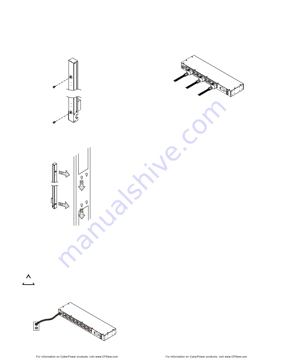
For 0U Model with Keyhole Mount
Step 1. Keyhole Mount Installation
Use the provided Screws (2) to attach the Keyhole Mounting
Pegs (2) to the PDU.
Installation Guide
Installation Guide
Step 2. PDU Mounting
Align the Keyhole Mounts to the Keyhole Slots on the rack. Insert
and slide down to lock firmly into the place.
CAUTION!!
The PDU must be plugged into a three-wire, grounded wall receptacle only. The wall
receptacle must also be connected to an appropriate branch circuit/main with fuse or
circuit breaker protection. Connection to any other type of wall receptacle may result
in a shock hazard.
Electrical Installation
Step 1 –Receptacle evaluation
Ensure that the plug type of your PDU unit matches the wall
receptacle type that you are using.
Step 2 – Plug the PDU into the wall receptacle
Step 3 – Attach equipment
It is extremely important not to exceed the PDUs maximum current
load (as outlined in the Specifications section). In order to determine
your total load, simply use the Metered Readout on the front of the PDU.
Step 1 – Attach the LAN Cable
Using a CAT5 RJ45 cable, attach one end to the Ethernet port on the front
of the PDU, and the other end to a network port.
Step 2 – Establish the PDU IP address
Assigning an IP address to the CyberPower PDU requires the user to have
an available IP address that is valid on the respective network.
If an available IP address is unknown, contact the network administrator to
obtain one.
The default IP is 192.168.20.177 and the default DHCP function is on.
There are multiple methods for setting up the IP address on the PDU. Please follow
the instructions below for the method that is appropriate for your application.
Please make sure the PDU is powered on during this process.
Option 1 (recommended): Power Device Network Utility
1. Use the included “PDU Software Installation CD” to install the Power Device
Network Utility program.
2. Open the Power Device Network Utility software (Start => Power Device Network Utility).
3. Highlight the PDU device from the list and select Edit and Setup device =>
Assisted Setup from the menu.
4. Configure the IP Address, Subnet Mask, and Gateway Address to match your
network settings.
5. Enter the user name and password of the PDU device at the Authentication menu.
Note : The default username is “
cyber
” and the default password is “
cyber
”.
For further information and installation instructions, see Appendix B.
Option 2: DHCP Server
1. Ask your administrator if there is DHCP server on the LAN.
2. Make sure the DHCP is Enabled.
3. Make sure the network connection is ready and power on the PDU.
4. The PDU will obtain an IP address from the DHCP server automatically.
Option 3: Address Resolution Protocol (ARP) Command
1. Obtain the MAC address from the sticker on the PDU.
2. Open a command prompt as an administrator and type the following:
“arp -s [available IP address] [MAC address of PDU]”.
Example: arp -s 192.168.20.240 00-0c-15-80-00-01
IP Address MAC Address
3. Use the Ping command to assign a size of 123 bytes to the IP.
* Type in “ping 192.168.20.240 -l 123” then press Enter
* If the replies are received, your computer can communicate with the IP address
Option 4: Hyper Terminal or Terminal Emulator
In order for Hyper Terminal to interface with the PDU, the PC/server must be
connected directly to the PDU via the serial port.
1. Use the included RJ45/DB9 serial port connection cable, attach one end to the
serial port on the front of the PDU, and the other end to the PC/ server.
2. Open the Hyper Terminal software on your PC and select a name and icon for
the connection.
3. Setup the COM port settings using the following values
* Bits per second: 9600
* Data bits: 8
* Parity: None
* Stop bits: 1
* Flow control: None
Network Installation


