17
18
Installation Guide
Operation
Operation
4. Type “setup” and press Enter to enter the Authentication menu.
5. Enter the user name and password of the PDU device at the Authentication menu.
Note:
The default username is “
cyber
” and the default password is “
cyber
”.
For further information and configuration via Hyper Terminal, see Appendix A-
Hyper Terminal.
Metered Readout
Tx/Rx
Link
Amps
Volts
KW
- Warning
- Overload
B1
B2
- Normal
Select
YU0-0000028-00
Reset
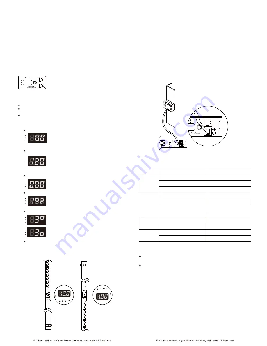
The Metered Readout provides instant status updates of the
PDU’s Voltage, Current, Power conditions as well as the local
IP address of the unit to the user. In addition, it also allows
the user to control each outlet of the PDU.
Basic Operation
Screen Selection- To toggle the different status screens, press the Select button
next to the PDU status screen.
Pressing the Select button once will toggle to the next status screen.
Pressing and holding the Select button for 3 seconds will display the
local IP address of the unit.
Pressing and holding the Select button for 6 seconds will enter the outlet
control mode.
PDU Status Screen
Current Level
Amps
Volts
KW
The Current Level screen shows the total current draw of the
connected equipment. Units are listed in Amps.
The Power screen shows the total power that the devices
connected to the PDU consumes. Units are listed in kilowatts.
The IP Address screen displays the local IP address of the
PDU unit. Note: If the PDU is not connected to a LAN, the
readout will display the default IP address.
The LED status screen can be set to display upside down from standard
through the Web Interface (as shown in figures below). Note: the decimal
point will not be moved and will instead be on the top if this option is enabled.
The Outlet screen shows the condition of each outlet in
sequence. When the outlet is on, the light below this outlet
will be on and a square appears in the upper right area next
to the number of the outlet. To switch the outlet off, press the
Select button once and the square will move to the lower
right. After 1 second, the outlet will turn off.
The Input Voltage screen measures the AC voltage that the
system is receiving from the utility wall receptacle. This can
be used as a diagnostic tool to identify poor-quality input
power. Units are listed in Volts.
Input Voltage
Power
Outlet Control (switched series only)
LED Reversal (0U series only)
CyberPower PDUs along with the environment sensor (ENVIROSENSOR)
provide the function of temperature and humidity monitoring in a server closet
and/or datacenter remotely. To connect the PDU with ENVIROSENSOR, use
the RJ45 Ethernet Cable. Plug one end into the Serial/ENVIROSENSOR port
on the PDU and the other end into the RJ45 port on the ENVIROSENSOR
(as shown in figures below). When the PDU correctly connects to the
ENVIROSENSOR, users can see the temperature and humidity data on the
Web Interface. For further information regarding ENVIROSENSOR
configuration please refer to the PDU Software Installation CD.
Environmental Monitoring (optional)
Amps
Volts
KW
Amps
Volts
KW
Amps
Volts
KW
Amps
Volts
KW
Amps
Volts
KW
IP Address
S
el
ec
t
KW
Vo
lts
A
mps
Tx
/Rx
Link
R
es
et
B1
B2
- N
ormal
- W
arni
ng
- Overl
oad
PD
U2
0SWV
T2
4FN
ET
S
ele
ct
KW
Vo
lts
A
mps
Tx
/Rx
Link
R
es
et
B1
B2
- N
ormal
- W
arni
ng
- Overl
oad
PD
U2
0SWV
T2
4FN
ET
KW
Volts
Amps
Reset
B1
KW
Volts
Amps
Reset
B1
8
Select
KW
Volts
Amps
- Normal
- Warning
- Overload
Tx/Rx
Link
Reset
YU0-0000033-01
PDU20SWT8FNET
Select
- Normal
- Warning
- Overload
Tx/Rx
Link
PDU20SWT8FNET
LED Indicators
s
u
t
a
t
S
r
o
t
a
c
i
d
n
I
Description
Green
The total PDU power load is normal.
Orange
Near overload.
Red
Overload.
.f
f
o
s
i
r
e
w
o
p
U
D
P
e
h
T
ff
O
On(Green)
The PDU power is on.
Receiving/transmitting data packet.
Reset finished.
.
N
A
L
e
h
t
o
t
d
e
t
c
e
n
n
o
c
s
i
U
D
P
e
h
t
s
e
t
a
c
i
d
n
I
n
O
Off
Indicates the PDU is not connected to the
LAN.
.
r
e
w
o
p
g
n
i
d
i
v
o
r
p
d
n
a
n
o
s
i
t
e
lt
u
o
e
h
T
n
O
.f
f
o
s
i
t
e
lt
u
o
e
h
T
ff
O
Outlet
Load
Tx/Rx
Flash
LINK
Device Reset
To reset all the settings to default except for the IP address, press and
hold the Reset Button for 3 seconds.
To reset all the settings to default, press and hold the Reset Button for 6
seconds.
Remote Management
The remote management function of the CyberPower PDU provides for
monitoring the PDU vitals, controlling outlets, and utilizing SNMP functionality.
Remote management is performed via the web interface. To access the web
interface, please follow the instructions below:
1. Enter the IP address of the PDU into a web browser (Internet Explorer, Firefox).
2. Enter the user name and password of the PDU device at the authentication screen.
Note:
The default username is ”
cyber
” and the default password is “
cyber
”.
For additional information about the features and functionality of CyberPower
Management Console, please refer to the PDU Software Installation CD.


