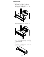
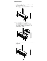
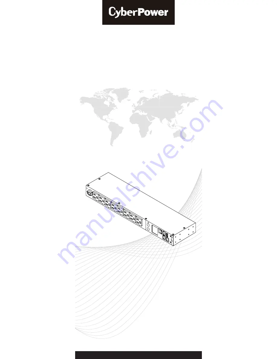
background image

Power Distribution Unit

USER'S MANUAL

Copyright © 2018 Cyber Power Systems, Inc. All rights reserved.                       K01-0000545-02

Summary of Contents for PDU31001

Page 1: ...Power Distribution Unit USER S MANUAL Copyright 2018 Cyber Power Systems Inc All rights reserved K01 0000545 02 ...

Page 2: ...s 15 Power Cord Direction Change For 0U PDU 19 Locking Power Cord For IEC Type PDU 20 Input Power Cord 20 Output Power Cord 20 Electrical Installation 20 Network Installation 2 1 Operation 22 Remote Management 22 Local Management 22 LED Indicators 23 Environmental Monitoring optional 23 Device Reset 23 Unattended Automatic Shutdown 23 Firmware Upgrade 24 Troubleshooting 28 Conformance Approvals 28...

Page 3: ... operating the Power Distribution Units PDU Use only the supplied hardware to attach the mounting brackets The PDU must be plugged into a three wire grounded outlet on a circuit that is protected by a fuse or circuit breaker For 15A PDU series please use a 15A circuit protector For 20A PDU series please use a 20A circuit protector For 30A PDU series please use a 30A circuit protector Connection to...

Page 4: ...ws 6 M5 x 12 Rack Mounting Screws Washers Cord Retention Tray 6 M3 x 6 Cord Retention Tray Mounting Screws Cable Ties Qty 12 NEMA outlet PDU Qty 27 IEC outlet PDU RJ45 DB9 Serial Port Connection Cable User s Manual Registration Card and Software Download Card Users Manual Registration Card PowerPanel Management Software ...

Page 5: ...ashers Cord Retention Tray x 2 12 M3 x 6 Cord Retention Tray Mounting Screws Cable Ties Qty 24 NEMA outlet PDU Qty 30 10 IEC outlet PDU Qty 48 16 IEC outlet PDU RJ45 DB9 Serial Port Connection Cable User s Manual Registration Card and Software Download Card Users Manual Registration Card PowerPanel Management Software Introduction ...

Page 6: ...ontents 0U Models PDU Mounting Brackets with 6 M4x5 Screws 6 M5 x 12 Rack Mounting Screws Washers Cord Retention Tray 6 M3 x 6 Cord Retention Tray Mounting Screws Cable Ties Qty 30 20 outlet PDU Qty 36 24 outlet PDU Qty 63 42 outlet PDU RJ45 DB9 Serial Port Connection Cable User s Manual Registration Card and Software Download Card Users Manual Registration Card PowerPanel Management Software Intr...

Page 7: ...cations UL 60950 1 FCC Class A UL 60950 1 CE FCC Class A All specifications are subject to change without notice A AC Inlet AC Power Cord Used to connect PDU to utility power or UPS B AC Output Receptacles Provides power for connected equipment C Status Indicator Indicates the condition of the PDU eg load or environment status D Multifunction LCD Readout Displays various PDU information such as po...

Page 8: ...he outlet is providing power to connected equipment Rear Panel Description A Ground Stud Use to ground the PDU Technical Specifications Model Name PDU81002 PDU71002 PDU41002 PDU31002 PDU81005 PDU71005 PDU41005 PDU31005 PDU81006 PDU71006 PDU41006 PDU31006 Input Nominal Voltage 100 120V 100 240V 200 240V Frequency 50 60Hz Maximum Input Current 16A CE UL Derated Plug Type NEMA L 5 20P Adapter IEC 320...

Page 9: ...tor switched series only Indicates if the outlet is providing power to connected equipment A Ground Stud Use to ground the PDU Technical Specifications Model Name PDU81003 PDU71003 PDU41003 PDU31003 PDU81007 PDU71007 PDU41007 PDU31007 PDU81008 PDU71008 PDU41008 PDU31008 PDU81009 PDU71009 PDU41009 PDU31009 Input Nominal Voltage 100 120V 200 240V Frequency 50 60Hz Maximum Input Current 24A UL Derate...

Page 10: ...r chaining to previous PDU G USB Port Used to upgrade the firmware via a flash drive H AC Output Receptacles Provides power for connected equipment I Serial Port RJ45 modular port Used to connect to a PC and control the PDU locally via SSH Telnet J Daisy Chain Out Port Used for chaining to next PDU K Select Button Used to control the LCD screen and toggle through the available information options ...

Page 11: ...5 m Output Nominal Voltage 100 120V 200 240V Maximum Input Current 16A UL Derated 16A CE 16A UL Derated 16A CE Outlet Type NEMA 5 20R 21 IEC C13 3 IEC C19 18 IEC C13 2 IEC C19 Outlet Number 24 21 3 18 2 Management and Communications Multifunction LCD Readout Voltage Frequency Load Current HW FW Version Network Information Software PowerPanel Business Edition Networking Yes Serial Port RJ45 Sensor ...

Page 12: ...Indicates the condition of the PDU eg load or environment status D Multifunction LCD Readout Displays various PDU information such as power and load condition E Ethernet Port Used to connect PDU to the network F ENVIROSENSOR Daisy Chain In Port RJ45 modular port Used for ENVIROSENSOR or chaining to previous PDU G USB Port Used to upgrade the firmware via a flash drive H AC Output Receptacles Provi...

Page 13: ...umber 24 21 3 36 6 Circuit Breaker Yes Management and Communications Multifunction LCD Readout Voltage Frequency Load Current HW FW Version Network Information Software PowerPanel Business Edition Networking Yes Serial Port RJ45 Sensor Capable Optional Physical Dimensions H x W x D 65 5 x 2 2 x 1 9 1665mm x 56mm x 48mm Environmental Humidity 0 to 95 Non condensing Altitude 11480 ft 3500 m Temperat...

Page 14: ...e provided Mounting Bracket Screws 8 to attach the SHORT Mounting Brackets 2 to the PDU Step 2 PDU Mounting Use the supplied Washers 4 and Screws 4 to secure the PDU to your existing rack system Note You may also use the screw sets provided by the rack to secure the PDU If you plan on attaching the Cord Retention Tray to the PDU you will need to use the LONG Mounting Brackets 2 ...

Page 15: ...l the screw hole on the Tray and PDU are aligned Attach the Cord Retention Tray to the PDU with the 4 supplied Cord Retention Tray Mounting Screws Tighten the Cord Retention Tray with the screw on it Use the provided Cable Ties to fasten each cord to the Cord Retention Tray Note If the PDUs are intended to install in a high temperature environment please use the Power Cords that could sustain high...

Page 16: ...te You may also use the screw sets provided by the rack to secure the PDU Step 3 Cord Retention Tray Installation optional Adjust the length of the Cord Retention Tray till the screw hole on the Tray and PDU are aligned Attach the Cord Retention Tray to the PDU with the 8 supplied Cord Retention Tray Mounting Screws Tighten the Cord Retention Tray with the screw on it Installation Guide ...

Page 17: ...ep 2 PDU Mounting Use the supplied Washers 2 and Screws 2 to secure the PDU to your existing rack system Note You may also use the screw sets provided by the rack to secure the PDU Vertical Installation For 1U Models Installation Guide For 0U Models Step 1 PDU Mounting Align the Keyhole Mounts to the Keyhole Slots on the rack Insert and slide down to lock firmly into the place ...

Page 18: ...hat is best for your rack deployment to secure the PDU Use the supplied Washers and Rack Mounting Screws to attach the Mounting Brackets to your existing rack system Align the Keyhole Mounts to the Keyhole Slots on the Mounting Brackets Insert and slide down to lock firmly into the place Method 1 Method 2 ...

Page 19: ...17 Method 3 Installation Guide ...

Page 20: ...ntion Tray to the PDU with the supplied Cord Retention Tray Mounting Screws Tighten the Cord Retention Tray with the screw on it Use the provided Cable Ties to fasten each cord to the Cord Retention Tray Note If the PDUs are intended to install in a high temperature environment please use the Power Cords that could sustain high temperature operation Installation Guide ...

Page 21: ...r Cord Direction Change For 0U PDU Step 1 Remove the four screws from the power cord cover Keep the screws for later use Step 2 Rotate the power cord cover Step 3 Install the power cord cover back to the PDU with the four screws ...

Page 22: ...Step 3 Attach equipment It is extremely important not to exceed the PDUs maximum current load as outlined in the Specifications section In order to determine your total load simply use the LCD screen on the front of the PDU to monitor the load being attached The PDU must be plugged into a three wire grounded wall receptacle only The wall receptacle must also be connected to an appropriate branch c...

Page 23: ...sword is cyber Option 2 DHCP Server 1 Ask your administrator if there is DHCP server on the LAN 2 Make sure the DHCP is Enabled 3 Make sure the network connection is ready and power on the PDU 4 The PDU will obtain an IP address from the DHCP server automatically Option 3 Address Resolution Protocol ARP Command 1 Obtain the MAC address from the sticker on the PDU 2 Open a command prompt as an admi...

Page 24: ...e CyberPower MIB file from www cyberpower com and add it to an SNMP supported management software Default read write community is public private for SNMPv1 SNMPv3 provides a higher security level than SNMPv1 by encrypting the transmitted packet Configure the settings of the SNMPv1 SNMPv3 on Web Interface Local Management LCD Operation The LCD screen provides instant information such as voltage cur...

Page 25: ...down on the connected computer s operating system PowerPanel must be installed on every computer or server for which the shutdown is to take place The computer will receive a message from the PDU and will perform the shutdown according to the instructions provided including shut downs at exact times and dates Step 1 Computer Configuration 1 Install PowerPanel Business Edition Client on every compu...

Page 26: ...te 1 The FTP service needs to be enabled before attempting to execute a firmware upgrade 2 Please do not turn the PDU off when performing the firmware upgrade PDU outlets will remain powered on while the firmware update takes place Only the PDU LCD screen will reboot 3 The PDU LCD screen will reboot during the firmware update process This DOES NOT cause the PDU outlets to reboot Option 1 Single De...

Page 27: ... following steps to upgrade the firmware 1 Download the Upgrade and Configuration Utility from www cyberpower com 2 Open Upgrade and Configuration Utility from Start All Programs CyberPower Upgrade and Configuration Utility 3 Wait for search to finish Shown in Figure 1 Figure 1 4 Check the checkbox to select devices listed in the Operation View Shown in Figure 2 Figure 2 5 Make sure Account and Pa...

Page 28: ... updated Shown in Figure 4 Firmware Upgrade Figure 4 8 Click OK in the Upgrade Firmware confirmation window Shown in Figure 5 9 The upgrade progress bar will show in Last Action column Shown in Figure 6 Figure 6 10 The result of firmware upgrade will show in Result column Shown in Figure 7 Figure 5 ...

Page 29: ...Main USB USB Firmware Firmware Firmware Firmware Upgrade Upgrade Upgrade Upgrade Main Confirm Processing Success Return Yes No Main Menu Alert Meter Control Sensor Setting About USB 4 Select USB and press Enter button to enter Firmware Upgrade menu 5 Select Main and Yes to start the upgrade process 6 The PDU will reboot after the process is completed Note You can check to see if the firmware upgra...

Page 30: ...mission limits and also to prevent interference to the nearby radio and television reception It is essential that only the supplied power cord by used 2 Use only shielded cables to connect I O devices to this equipment Note THE MANUFACTURER IS NOT RESPONSIBLE FOR ANY RADIO OR TV INTERFERENCE CAUSED BY UNAUTHORIZED MODIFICATIONS TO THIS EQUIPMENT SUCH MODIFICATIONS COULD VOID THE USER S AUTHORITY T...

Page 31: ...Product If the Product is defective in material or workmanship CyberPower will repair or replace it at CyberPower s expense or if CyberPower is unable to or decides not to repair or replace the Product if defective within a reasonable time CyberPower will refund to you the full purchase price you paid for the Product purchase receipt showing price paid is required Who Pays for Shipping We pay when...

Page 32: ... Configuration 4 Account Settings 5 Configure System to Default 6 Logout Outlet Manager 1 Outlet Control 2 Outlet Configuration Network Setting Physical MAC Address 00 0C 15 40 08 A9 1 System IP 192 168 24 20 2 Subnet Mask 255 255 255 0 3 Default Gateway 192 168 24 254 4 DHCP Enabled 5 Http Port 80 6 Http Access Enabled System Configuration 1 Date mm dd yyyy 11 11 2011 2 Time hh mm ss 17 17 25 3 N...

Page 33: ...y Step 3 Choose an installation directory Select Next Shown in Figure 2 Figure 2 Step 4 Select Install to confirm the settings and install Shown in Figure 3 Figure 3 Step 5 Select Finish to finalize the installation Shown in Figure 4 Figure 4 ...

Page 34: ...his allows the device s to function properly on the network and interface with CyberPower Management Console Step 1 Select the appropriate PDU device from the Equipment List Shown in Figure 6 Figure 6 Equipment List Figure 5 Power Device Network Utility Note If the PDU does not appear on the list click the Refresh button to rescan the network If it still does not appear ensure that the PDU is turn...

Page 35: ...vice at the Authentication menu Shown in Figure 9 Note The default username is cyber and the default password is cyber Advanced Settings Timeout Settings The Timeout Setting Shown in Figure 10 Edit Timeout Settings is used to specify the wait time when scanning for network PDU devices When there are many devices on the local network it may take extended periods of time to locate all the devices Th...

Page 36: ... Ethernet cable and connect one end of it to the daisy chain Out port on the Host PDU and the other end to the daisy chain In ENV port on the Guest 1 PDU to connect the PDUs as shown below ain Function Introduction xx 41xxx 31xxx our PDUs to be connected together to IP address re defined Host and Guest Up to three Host PDU The Guest PDUs will be order within the daisy chain ion the firmware versio...

Page 37: ...ble between Guest 1 and 2 is re connected Guest 2 and 3 will revert to their previous roles What happens if one PDU in the daisy chain is powered off For example if four PDUs are connected and Guest 1 is powered off an event showing that Guest 1 2 and 3 are removed will be recorded in the Host PDU Guest 2 and 3 will not create another daisy chain Does the Host PDU record the logs of the Guest PDUs...

Page 38: ... chained Yes even when the PDUs are daisy chained the Guest PDUs are able to connect to the network directly Note that a Guest PDU will require having its own Ethernet cable connected to the network What will happen if a 5th PDU is added to a daisy chain The maximum number of PDUs that can be connected in one daisy chain is 4 The daisy chain functionality will not work until the fifth PDU is remov...

Page 39: ...Cyber Power Systems Inc www cyberpower com Copyright 2018 Cyber Power Systems Inc All rights reserved K01 0000545 02 ...

Reviews: