background image

  Chapter 2 Installation Instruction


28 

SM 180-600 KMFX User Manual 

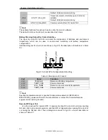
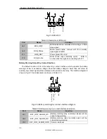
Port 

Name 

Function 

J10-1 

UTILITY_FAIL_NC 

Mains  failure  warning  relay(normally  closed)  will 
be open during warning 

J10-2 

UTILITY_FAIL_NO 

Mains  failure  warning  relay  (normally  open)  will 
be closed during warning 

J10-3 

UTILITY_FAIL_GND 

Common terminal 


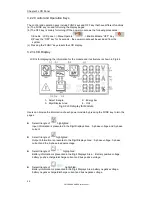
2.7.2 Communication Interface 

RS232

RS485 and USB port

Provide serial data which can be used for commissioning 

and  maintenance  by  authorized  engineers  or  can  be  used  for  networking  or  integrated 
monitoring system in the service room.   
SNMP: Used on site installation for communication (Optional).   

Intelligent card interface

Extension dry contact interface (Optional).

Summary of Contents for SM180KMFX

Page 1: ...User s Manual SM30KPMX SM180KMFX SM300KMFX SM600KMFX CyberPower Systems Inc www cyberpower com ...

Page 2: ...Ver 1 0 2 ...
Page 3: ...amiliar with the operation debug and maintenance of the equipment Warning Label The warning label indicates the possibility of human injury or equipment damage and advises the proper step to avoid the danger In this manual there are three types of warning labels as below Labels Description Danger Serious human injury or even death may be caused if this requirement is ignored Warning Human injury o...

Page 4: ... 10 minutes for internal discharge Use a multi meter to measure the voltage on terminals and ensure the voltage is lower than 36V before operation Attention The earth leakage current of load will be carried by RCCB or RCD Initial check and inspection should be performed after long time storing of UPS Maintenance Replacement Danger All the equipment maintenance and servicing procedures involving in...

Page 5: ...osion or poor performance When connecting the battery follow the precautions for high voltage operation before accepting and using the battery check the appearance the battery If the package is damaged or the battery terminal is dirty corroded or rusted or the shell is broken deformed or has leakage replace it with new product Otherwise battery capacity reduction electric leakage or fire may be ca...

Page 6: ...out of control swell or leak Be sure to replace the battery before these phenomena happen If a battery leaks electrolyte or is otherwise physically damaged it must be replaced stored in a container resistant to sulfuric acid and disposed of in accordance with local regulations If electrolyte comes into contact with the skin the affected area should be washed immediately with water Disposal Warning...

Page 7: ...the Cabinet 11 2 2 2 Unpacking Power Module 11 2 3 Positioning 13 2 3 1 Positioning Cabinet 13 2 3 2 Installing Power Module 11 2 4 Battery 16 2 5 Cable Entry 16 2 6 Power Cables 19 2 6 1 Specifications 19 2 6 2 Specifications for Power Cables Terminal 19 2 6 3 Circuit Breaker 20 2 6 4 Connecting Power Cables 20 2 7 Control and Communication Cables 22 2 7 1 Dry Contact Interface 23 2 7 2 Communica...

Page 8: ...ypass Unit for 20 slot Cabinet 56 5 3 3 Maintenance for the Air drawing fans 56 5 3 4 Battery Maintenance 56 5 3 5 Disconnect the Inner Control Neutral cable 57 5 4 Battery Setting 57 5 4 1 Battery Setting 58 5 4 2 Setting of Battery Number 58 5 4 3 Battery Capacity Setting 58 5 4 4 Float and Boost Charge Setting 58 5 4 5 EOD Voltage Setting 59 5 4 6 Charging Current Percent Limit 59 5 4 7 Battery...

Page 9: ...s Bypass Monitoring module and cabinet with manual Bypass switch One or several battery strings should be installed to provide backup energy once the utility fails The UPS structure is shown in Fig 1 1 Rectifier AC DC Main Static Bypass Manual Bypass Inverter DC AC Charge Discharge Output Battery Bypass Fig 1 1 6 slot and 10 slot UPS Configuration Fig 1 2 20 slot UPS Configuration ...

Page 10: ...e 1 3 1 Normal Mode The inverter of power modules continuously supply the critical AC load The rectifier charger derives power from the AC mains input source and supplies DC power to the inverter while simultaneously FLOAT or BOOST charging its associated backup battery Rectifier AC DC Main Static Bypass Manual Bypass Inverter DC AC Charger DC DC Output Battery Bypass Fig 1 4 Normal mode operation...

Page 11: ... will perform a transfer of the load from the inverter to the bypass with power interruption to the load This is to avoid large cross currents due to the paralleling of unsynchronized AC sources This interruption is programmable but typically set to be less than 3 4 of an electrical cycle e g less than 15ms 50Hz or less than 12 5ms 60Hz The action of transfer re transfer can also be done by the co...

Page 12: ...r is standby When the utility fails the UPS transfers to Battery Mode and the inverter provide powers to the loads Rectifier AC DC Main Static Bypass Manual Bypass Inverter DC AC Charger DC DC Output Battery Bypass Fig 1 8 ECO Mode operation diagram Note There is a short interruption time less than 10ms when transfer from ECO mode to battery mode it must be sure that the interruption has no effect...

Page 13: ...ration Item Components Quantity pcs Remark 6 slot Cabinet Manual Bypass 1 Requisite factory installed Bypass Monitoring module 1 Requisite factory installed Dust filter 1 Optional 10 slot Cabinet Manual Bypass Requisite factory installed Bypass Monitoring module 1 Requisite factory installed Dust filter 1 Optional 20 slot Cabinet Power distribution cabinet CB of Input Bypass Input Output and Manua...

Page 14: ...pter 1 Product Introduction 6 SM 180 600 KMFX User Manual Fig 1 9 Outlook of 6 slot UPS Fig 1 10 Outlook of 10 slot UPS Fig 1 11 Outlook of 20 slot UPS The UPS front view are shown in Fig 1 12 to Fig 1 14 ...

Page 15: ...nt view of 10 slot UPS Fig 1 14 Front view of 20 slot UPS LCD control panel SPD Manual Bypass switch Battery cold start Monitoring static bypass module Monitoring unit Static Bypass unit Output switch of 20 slot cabinet Q3 Input switch of 20 slot cabinet Q1 The UPS back view are shown in Fig 2 15 to Fig 2 17 ...

Page 16: ...uction 8 SM 180 600 KMFX User Manual Fig 1 15 Back view of 6 slot UPS Fig 1 16 Back view of 10 slot UPS Fig 1 17 Back view of 20 slot UPS PDU Bypass Input switch of 20 slot cabinet Q3 Manual bypass switch of 20 slot cabinet Q3 ...

Page 17: ...nsure the fresh air volume of the battery installation environment must meet EN50272 2001 requirements If external batteries are to be used the battery circuit breakers or fuses must be mounted as close as possible to the batteries and the connecting cables should be as short as possible 2 1 2 Site Selection Ensure the ground or installation platform can bear the weight of the UPS cabinet batterie...

Page 18: ...net b 10 slot cabinet c 20 slot cabinet Fig 2 1 Space reserved for the cabinet Unit mm The dimension and weight for the UPS cabinet is shown in Table 2 1 Table 2 1 Weight for the cabinet Configuration Dimension W D H mm Weight Kg 6 slot Cabinet with bypass module 600 1100 1600 170 ...

Page 19: ...ng 2 2 1 Moving and Unpacking of the Cabinet The steps to move and unpack the cabinet are as follows 1 Check if any damages to the packing If any contact to the carrier 2 Transport the equipment to the designated site by forklift as shown in Fig 2 2 Fig 2 2 Transport to the designated site 3 Open the top plate of the steel edged wooden case with slotted awl and pier followed by side boards see Fig...

Page 20: ...luded in the list contact to our company or the local office 6 Dismantle the bolt that connects the cabinet and wooden pallet after disassembly 7 Move the cabinet to the installation position Attention Be careful while removing to avoid scratching the equipment 2 2 2 Unpacking Power Module 1 The steps to move and unpack the power module are as follows 2 The packing case must be placed on the platf...

Page 21: ...ials of unpacking should be disposed to meet the demand for environmental protection 2 3 Positioning 2 3 1 Positioning Cabinet The UPS cabinet has two way of supporting itself One is to support itself temporarily by the 4 wheels at the bottom 12 for the 20 slot making it convenient to adjust the position of the cabinet The other is by anchor bolts to support the cabinet permanently after adjusting...

Page 22: ...re is in good condition and the mounting floor is smooth and strong 2 Retract the anchor bolts by turning them counterclockwise using wrench the cabinet is then supported by the four wheels 3 Adjust the cabinet to the right position by the supporting wheels 4 Put down the anchor bolts by turning them clockwise using wrench the cabinet is then supported by the four anchor bolts 5 Ensure the four an...

Page 23: ... The steps of installing power module are as follows Take the 10 slot cabinet as example 1 Ensure the cabinet is fixed and no damage to the body and inserting port of the power module 2 Hold the handler and the body of the power module by two persons at each side 3 Insert the module in the installation position and push it into the cabinet smoothly 4 Fix the module to the cabinet though the mounti...

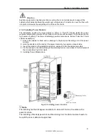
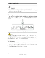
Page 24: ... 2 9 N N 40 batteries in series 40 39 21 Fig 2 9 Battery string wiring diagram Danger The battery terminal voltage is of more than 400Vdc please follow the safety instructions to avoid electric shock hazard Ensure the positive negative neutral electrode is correctly connected from the battery unit terminals to the breaker and from the breaker to the UPS system 2 5 Cable Entry For the 6 slot and 20...

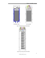
Page 25: ...Chapter 2 Installation Instruction 17 SM 180 600 KMFX User Manual a Bottom entry b Top entry Fig 2 10 Cable entry for 6 slot cabinet Fig 3 11 Top entry for 10 slot cabinet ...

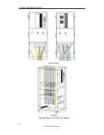
Page 26: ...Chapter 2 Installation Instruction 18 SM 180 600 KMFX User Manual Bottom entry Top entry Fig 3 12 Cable entry for 20 slot cabinet ...

Page 27: ...ns described below Ambient temperature 30 AC loss less than 3 DC loss less than 1 The length of the AC power cables are no longer than 50 m and the length of the DC power cables are no longer than 30 m Currents listed in the table are based on the 380V system Line to line voltage For 400 V system the currents is 0 95 times and for the 415V system the current is 0 92 times The size of neutral lines...

Page 28: ...6 slot cabinet 10 slot cabinet 20 slot cabinet Input CB 300A 3P 600A 3P Bypass Input CB 250A 3P 500A 3P Output CB 250A 3P 500A 3P Battery CB 400A 500Vdc 800A 500Vdc 1250A 500Vdc For the 20 slot cabinet the Main Input Bypass Input and Output CB are installed in the Cabinet Attention The CB with RCD Residual Current Device is not suggested for the system 2 6 4 Connecting Power Cables The steps of co...

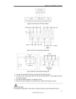
Page 29: ...protective earth wire to protective earth terminal PE 4 Connect the AC input supply cables to the Input terminal and AC output supply cables to the Output terminal 5 Connect the Battery cables to the Battery terminal 6 Check to make sure there is no mistake and re install all the protective covers Attention The operations described in this section must be performed by authorized electricians or ...

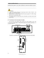
Page 30: ...nings label to warn not to operate by others The grounding cable and neutral cable must be connected in accordance with local and national codes 2 7 Control and Communication Cables The front panel of the bypass module provides dry contact interface J2 J11 and communication interface RS232 RS485 SNMP Intelligent card interface and USB port as it is shown in Fig 2 14 Fig 2 16 Dry contact communicat...

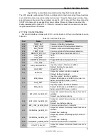
Page 31: ...when disconnect with J4 2 J4 2 24V_DRY 24V J4 3 24V_DRY 24V J4 4 REMOTE_EPO_NO Trigger EPO when shorted with J4 3 J5 1 24V_DRY 24V J5 2 GEN_CONNECTED Input dry contact function is settable Default interface for generator J5 3 GND_DRY Ground for 24V J6 1 BCB Drive Output dry contact function is settable Default Battery trip signal J6 2 BCB_Status Input dry contact function is settable Default BCB S...

Page 32: ... J2 and J3 are shown in Fig 2 15 the description of interface is in Table 2 6 J2 J3 TEMP_BAT TEMP_ENV Fig 2 15 J2 and J3 for temperature detecting Table 2 6 Description of J2 and J3 Port Name Function J2 1 TEMP_BAT Detection of battery temperature J2 2 TEMP_COM Common terminal J3 1 ENV_TEMP Detection of environmental temperature J3 2 TEMP_COM Common terminal Note Specified temperature sensor is re...

Page 33: ...rator J5 Connect pin 2 of J5 with 24V power supply it indicates that the generator has been connected with the system The interface diagram is shown in Fig 2 17 and interface description is shown in Table 2 8 J5 GEN 24V AUX N O AUX N O Generator Fig 2 17 Diagram of status interface and connection of generator Table 2 8 Description of status interface and connection of generator Port Name Function ...

Page 34: ...The default function of J8 is the output dry contact interface which presents the battery warnings of low or excessive voltage when the battery voltage is lower than set value an auxiliary dry contact signal will be activated via the isolation of a relay The interface diagram is shown in Fig 2 19 and description is shown in Table 2 10 J8 BAT_LOW_NC BAT_LOW_N O GND Fig 2 19 Battery warning dry cont...

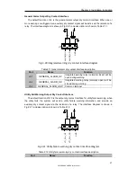
Page 35: ..._NC Integrated warning relay normally closed will be open during warning J9 2 GENERAL_ALARM_NO Integrated warning relay normally open will be closed during warning J9 3 GENERAL_ALARM_GND Common terminal Utility Fail Warning Output Dry Contact Interface The default function of J10 is the output dry contact interface for utility failure warning when the utility fails the system will send a utility f...

Page 36: ...lly open will be closed during warning J10 3 UTILITY_FAIL_GND Common terminal 2 7 2 Communication Interface RS232 RS485 and USB port Provide serial data which can be used for commissioning and maintenance by authorized engineers or can be used for networking or integrated monitoring system in the service room SNMP Used on site installation for communication Optional Intelligent card interface Exte...

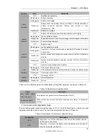
Page 37: ...o indicate the statuses and faults by combinations of different colors and the time it lasts The combinations are listed in Table 3 1 Table 3 1 Statues and faults of different combinations No LED combinations Description 1 Green short time flashing 1 Green for 1S Off for 2S Rectifier soft starting 2 Green short time flashing 2 Green for 2S Off for 1S Inverter soft starting 3 Green medium time flas...

Page 38: ...iangle 2 Energy bar 3 Digit Display Area 4 Unit Fig 3 2 LCD display for Module Users can browse the information of each power module by pressing the FUNC key to turn the pages Select triangle of highlighted Input information is presented in the Digit Displays Area 3 phase voltage and 3 phase current Select triangle of highlighted Output information is presented in the Digit Displays Area 3 phase v...

Page 39: ...nected Energy bar of a Lightened Discharging mode b Off battery not connected or charging Unit Voltage V Current A Percentage When one power module is turning page the other modules update within 2 seconds Table 3 2 codes for faults and warnings Codes Description Codes Description 16 Main voltage abnormal 67 Battery polarity reversed 18 Bypass phase sequence fault 69 Inverter protected 20 Bypass v...

Page 40: ...arm Buzzer 4 Status indicator 5 Bypass indicator 6 Rectifier indicator 7 Inverter indicator 8 Load indicator 9 Battery indicator 10 Bypass transfer 11 Inverter transfer 12 Mute Fig 3 3 Control and display panel for cabinet The LCD panel for cabinet is divided into three functional areas LED indicator control and operation keys and LCD touch screen 3 3 1 LED Indicator There are 6 LEDs on the panel ...

Page 41: ...ault for at least one module Off Inverter not operating for all modules Load indicator Steady green UPS output ON and normal Steady red UPS overload time is out or output short or output no power supply Flashing red Overload output of UPS Off No output of UPS Status indicator Steady green Normal operation Steady red Failure There are two different types of audible alarm during UPS operation as sho...

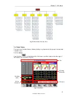
Page 42: ...ation display warning information and main menu Status bar The Status bar contains the model of the product capacity operational mode and the number of the power module and the time of the system Warning Information Display the warning information of the cabinet Information Display Users can check the information of the cabinet in this area The bypass voltage main input voltage battery voltage and...

Page 43: ...ncludes Cabinet Module Setting Log Operate and Scope and it is described in details below 3 4 1 Cabinet Touch the icon At the bottom left of the screen and the system enters the page of the Cabinet as it is shown in Fig 3 6 Operating status Version information Title Operating information Sub menu Fig 3 6 Cabinet ...

Page 44: ...he absent of the block and red indicating the absence of the block or in fault Version Information The version information for LCD of the cabinet and monitor Submenu It includes the submenu of Bypass Main Output load and battery Information display Display information of each submenu The interface of each submenu is shown in Fig 3 7 a Interface of Main b Interface of Output c Interface of Load d I...

Page 45: ...tage compared with new battery capacity Remain T Min Remaining battery backup time Battery Battery Temp Ambient Environmental Temp Total Work T Total work time Total Discharge T Total discharging time 3 4 2 Module Touch the icon At the bottom left of the screen and the system enters the page of the Module as is shown in Fig 3 8 Power module informatuion Version information Title Operating informat...

Page 46: ...and the rectifier and inverter are working normally The battery is not connected Version Information The version information for rectifier and inverter of the selected module Submenu The submenu includes Input Output Load INFO and S CODE Users can enter the interface of each submenu by directly touching the icon Each interface of the submenu is shown in Fig 3 9 a Interface of Output b Interface of...

Page 47: ...ative Charger V Charger Voltage Positive Negative Fan Time Total Fan s Running time of the selected power module Inlet Temperature C Inlet Temperature of the selected power module Outlet Temperature C Outlet Temperature of the selected power module S code Fault Code For the maintenance personnel 3 4 3 Setting Touch the icon At the bottom of the screen and the system enters the page of the Setting ...

Page 48: ... Down limited working Voltage for Bypass settable 10 15 20 30 40 Bypass Frequency Limited Permitted working Frequency for Bypass Settable 1Hz 3Hz 5Hz Dust Filter Maintenance Period Setting Dust Filter Maintenance Period BATTERY Battery Number Setting the number of the battery 12V Battery Capacity Setting of the AH of the battery Float Charge Voltage Cell Setting the floating Voltage for battery ce...

Page 49: ... CONFIGURE a Three level password is needed and it is set only by the factory The C stands for Ampere number For instance if the battery is 100AH then C 100A Warning Ensure the number of the battery set via the menu or the monitoring software is completely equal to the real installed number Otherwise it will cause serious damage to the batteries or the equipment 3 4 4 Log Touch the icon At the bot...

Page 50: ... Battery Voltage 6 Battery Discharge Set Battery is Discharging 7 Battery Connected Set Battery cables Connected 8 Battery Not Connected Set Battery cables Disconnected 9 Maintenance CB Closed Set Maintenance CB is Closed 10 Maintenance CB Open Set Maintenance CB is Open 11 EPO Set Emergency Power Off 12 Module On Less Set Valid Inverter capacity is less than the load capacity 13 Module On Less Cl...

Page 51: ...le Inverter Fail 47 Inverter Fail Clear Event above disappears 48 Rectifier Over Temp Set N Power Module Rectifier Over Temperature 49 Rectifier Over Temp Clear Event above disappears 50 Fan Fail Set N Power Module Fan Fail 51 Fan Fail Clear Event above disappears 52 Output Overload Set N Power Module Output Over Load 53 Output Overload Clear Event above disappears 54 Inverter Overload Tout Set N ...

Page 52: ...Detect Fail Set Battery Voltage is abnormal 86 Batt Volt Detect Fail Clear Event above disappears 87 Output Volt Fail Set Output Voltage is abnormal 88 Output Volt Fail Clear Event above disappears 89 Outlet Temp Error Set Outlet Temperature is abnormal 90 Outlet Temp Error Clear Event above disappears 91 Input Curr Unbalance Set Input current is not balance 92 Input Curr Unbalance Clear Event abo...

Page 53: ...the Operate as it is shown in Fig 3 12 Fig 3 12 Operate menu The Operate menu includes FUNCTION BUTTON and TEST COMMAND The contents are described in details below FUNTION BUTTON Clear Restore Buzzing Mute or Restore buzzing of the system by touching the icon or Fault Clear Clear the faults by touching the icon Transfer to and ESC Bypass Transfer to bypass mode or cancel this command by touching t...

Page 54: ...Battery mode to test the condition of the battery Ensure the bypass is working normally and the capacity of the battery is no less than 25 Battery Maintenance By touching the icon the system transfers to the Battery mode This function is used for maintaining the battery which requires the normality of the bypass and minimum capacity of 25 for the battery Battery Boost By touching the icon the syst...

Page 55: ...voltage by touching the corresponding icon in the left side of the interface The waves can be zoomed in and zoom out Touch the icon to display the 3 phase output voltage Touch the icon to display the 3 phase output current Touch the icon to display the 3 phase bypass voltage Touch the icon to zoom in the wave Touch the icon to zoom out wave ...

Page 56: ...eady green presenting the finishing of rectification and bypass static switch closes then the inverter is starting up The LED indicators are listed below in Table 4 2 Table 4 2 Inverter starting up Indicator Status Indicator Status Rectifier green Inverter green flashing Battery red Load green Bypass green Status red 6 The UPS transfers from the bypass to inverter after the inverter goes normal Th...

Page 57: ...ig 4 1The position of the battery cold start button for 10 slot cabinet Fig 4 2 the position of the battery cold start button for 20 slot cabinet 3 After that the system is starting up following steps 3 in section 5 1 1 and the system transfers to battery mode in 30S 4 Close the external output power supply isolation to supply the load and the system is working on battery mode 4 2 Procedure for Sw...

Page 58: ...ansfers to Normal mode Note Normally the system will transfer to the Normal mode automatically This function is used when the frequency of the bypass is over track and when the system needs to transfer to Normal mode by manual 4 2 4 Switching the UPS from Normal Mode into Maintenance Bypass Mode These following procedures can transfer the load from the UPS inverter output to the maintenance bypass...

Page 59: ...he LED touch screen goes on the bypass indicator goes green and the load is powered through maintenance bypass and static bypass 2 Turn off the maintenance bypass switch and the load is powered through bypass The rectifier starts followed by the inverter 3 After 60S the system transfers to Normal mode 4 3 Battery Maintenance If the battery is not in use for a long time it is necessary to test the ...

Page 60: ...00 if not the system will not start the process automatically 4 4 EPO The EPO button located in the operator control and display panel with cover to avoid disoperation see Fig 5 6 is designed to switch off the UPS in emergency conditions e g fire flood etc To achieve this just press the EPO button and the system will turn off the rectifier inverter and stop powering the load immediately including ...

Page 61: ...em it can have three UPS cabinets in parallel which can extend to a capacity of total 900KVA Howerever for the 20 slot system parallel is not supported at present Two UPS cabinets are connected as is shown in Fig 4 6 Fig 4 6 Parallel diagram The parallel board is located at the back of the UPS cabinet whose name is PS1203 TF4 as is shown in Fig 4 7 ...

Page 62: ...allel board The control cables for the parallel operation must be connected with all single devices to form a closed loop as is shown in Fig 4 8 Fig 4 8 Parallel connection For more details of parallel operation please refer to the Instruction for Parallel Operation of Modular UPS ...

Page 63: ...rsons 4 Wait 10 mins before opening the cover for repairing 5 After the repairing is done push the power module into the cabinet following the steps in section 3 3 2 and the power module will automatically join the system 5 3 Instruction for Maintaining 5 3 1 Maintaining Bypass Module for 6 slot and 10 slot Cabinet Confirm the UPS is operating in Normal mode and the bypass is working normally befo...

Page 64: ...al mode which indicates the maintenance is done successfully Note If it needs to take out the static bypass unit to do the repair a forklift is suggested The weight of the static bypass unit can be 55kg 5 3 3 Maintenance for the Air drawing fans 1 Take out the fan unit panel 2 Push the button of the fans to turn off the fans 3 Change the fans 4 Push the button to turn on the fans again 5 Install t...

Page 65: ...he inner control neutral cable The Inner Control Neutral Cable is located in the right of the maintenance bypass and is protected by the protective board as is shown in Fig 5 1 Fig 5 1 the position of Inner Control Neutral cable 5 4 Battery Setting The setting of battery needs to be done after the first time of powering off or any changes done on the batteries The battery configuration can be done...

Page 66: ...etting range is 140 180 The lowest EOD voltage for the LFPB will be 360V and highest voltage can be 620V 5 4 3 Battery Capacity Setting Battery Capacity Setting sets the capacity value of the battery block For example if the system uses 40 blocks of 12V 100AH batteries the Battery Capacity Setting should set to 100 Ah If 240 cells of 2V 1000AH are used the Battery Capacity Setting should be set to...

Page 67: ...is also limited to the battery capacity 5 4 7 Battery Temperature Compensate This is for setting the temperature compensate coefficient Based on 25 when the temperature is higher than that the discharging voltage goes lower When the temperature is lower than that the discharging voltage goes higher 5 4 8 Boost Charge Time Limit This is for setting the Boost Charge time When the set time is up the ...

Page 68: ... and give warning of overheat The set range is 25 70 The temperature sensor should be placed through the Dry Contact 5 5 Replacing Dust Filter optional As shown in Fig 5 6 there are 3 4 dust filters on the back of UPS front door each filter is held in place by a bracket on either side of each filter The procedure of replacing each filter is as follows 1 Open the front door and locate the filters o...

Page 69: ...3 VFI SS 111 Note The above mentioned product standards incorporate relevant compliance clauses with generic IEC and EN standards for safety IEC EN AS60950 electromagnetic emission and immunity IEC EN AS61000 series and construction IEC EN AS60146 series and 60950 6 2 Environmental Characteristics Table 6 2 Environmental Characteristics Item Unit Requirements 180kVA 300kVA 600kVA Acoustic noise le...

Page 70: ...s Input Rectifier Table 6 5 Rectifier AC input Mains Item Unit Parameter Grid System 3 Phases Neutral Ground Rated AC Input Voltage Vac 380 400 415 three phase and sharing neutral with the bypass input Rated Frequency Vac 50 60Hz Input voltage range Vac 304 478Vac Line Line full load 228V 304Vac Line Line load decrease linearly according to the min phase voltage Input Frequency range Hz 40 70 Inpu...

Page 71: ... discharge current EOD voltage changes linearly within the set range according to discharge current Battery Charge V cell 2 4V cell selectable from 2 3V cell 2 45V cell Constant current and constant voltage charge mode Battery Charging Power Max Current kW 10 UPS capacity selectable from 1 20 UPS capacity 6 4 3 Electrical Characteristics Inverter Output Table 6 7 Inverter Output To critical load I...

Page 72: ...60 Switch time between bypass and inverter ms Synchronized transfer 0ms Bypass voltage range Settable default 20 15 Up limited 10 15 20 25 Down limited 10 15 20 30 40 Bypass frequency range Hz Settable 1Hz 3Hz 5Hz Synchronized Range Hz Settable 0 5Hz 5Hz default 3Hz 6 5 Efficiency Table 6 9 Efficiency System Efficiency Normal mode dual conversion 95 Battery discharging efficiency battery at nomina...

Reviews: