29
SM 180-600 KMFX User Manual
Chapter 3 LCD Panel
Chapter 3 LCD Panel
3.1 Introduction
This chapter introduces the functions and operator instructions of the operator control and
display panel in detail, and provides LCD display information, including LCD display types,
detailed menu information, prompt window information and UPS alarm information.
3.2 LCD panel for Power Module
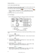
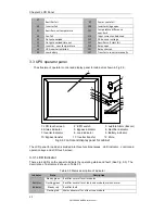
The structure of LCD panels for power module is shown in Fig.3-1.
1
:
Status indicator 2
:
LCD Display
3
:
OFF Key 4
:
FUNC Key
Fig.3-1 Control and display panel for power module
The operator control panel is divided into three functional areas
:
Status indicator
,
control and
operation keys and LCD display.
3.2.1 LED Indicator
The LED indicator has green and red colors to indicate the statuses and faults by
combinations of different colors and the time it lasts. The combinations are listed in Table 3.1
Table 3.1 Statues and faults of different combinations
No.
LED combinations
Description
1
Green short-time flashing 1
(Green for 1S
,
Off for 2S)
Rectifier soft starting
2
Green short-time flashing 2
(Green for 2S
,
Off for 1S)
Inverter soft starting
3
Green medium-time flashing
(Green for 1S
,
Off for 5S)
Power module inverter standby
4
Green long-time flashing
(Green for 2S
,
Off for 10S)
Power module in deep sleep (shutdown)
5
Steady green
UPS is working normally
6
Red and Green Alternating
(Red for 1S,Green for 5S)
The load powered by inverter with warnings
(
No battery
,
battery discharging, overload etc.
)
7
Steady red
Power module shutdown by fault
8
Red medium-time flashing
(Red for 1S
,
Off for 5S)
Shutdown manually or by monitoring software
9
Red short-time flashing
(Red for 1S
,
Off for 1S)
Situation except above
1
2
3
4
Summary of Contents for SM180KMFX
Page 2: ...Ver 1 0 2 ...

