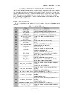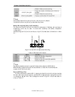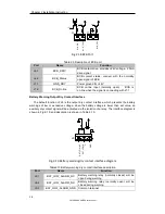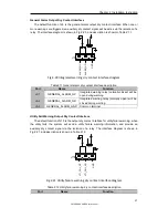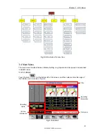
Chapter 3 LCD Panel
32
SM 180-600 KMFX User Manual
47
Rectifier fail
97
Power share fail
49
Inverter fail
109
Inverter bridge open
51
Rectifier over temperature
111
Temperature difference
over limit
53
Fan fail
113
Input current unbalanced
55
Output overload
115
DC bus over voltage
57
Output overload time out
117
Rectifier soft start fail
59
Inverter over temperature
119
Relay open
61
UPS inverter Inhibited
121
Relay shorted
65
Low battery
127
Transfer to inverter manually
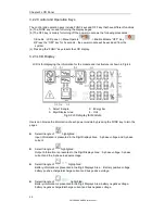
3.3 UPS operator panel
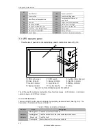
The structure of operator control and display panel for cabinet is shown in Fig.3-3.
1: LCD touch screen 2: EPO switch 3: Audible Alarm (Buzzer)
4: Status indicator 5: Bypass indicator 6: Rectifier indicator
7: Inverter indicator 8: Load indicator 9: Battery indicator
10: Bypass transfer 11: Inverter transfer 12: Mute
Fig.3-3 Control and display panel for cabinet
The LCD panel for cabinet is divided into three functional areas
:
LED indicator
,
control and
operation keys and LCD touch screen.
3.3.1 LED Indicator
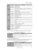
There are 6 LEDs on the panel to indicate the operating status and fault. (See Fig. 3-3). The
description of indicators is shown in Table 3.3
Table 3.3 Status description of indicator
Indicator
State
Description
Rectifier
indicator
Steady green
Rectifier normal for all modules
Flashing green Rectifier normal for at least one module, mains normal
Steady red
Rectifier fault
Flashing red
Mains abnormal for at least one module
1
2
3
4
6
7
8
9
5
BYP
INV
MUTE
10
11
12
Summary of Contents for SM180KMFX
Page 2: ...Ver 1 0 2 ...

