Chapter 2 Installation Guidance
Smart Tower UPS 10-30KVA User Manual
8
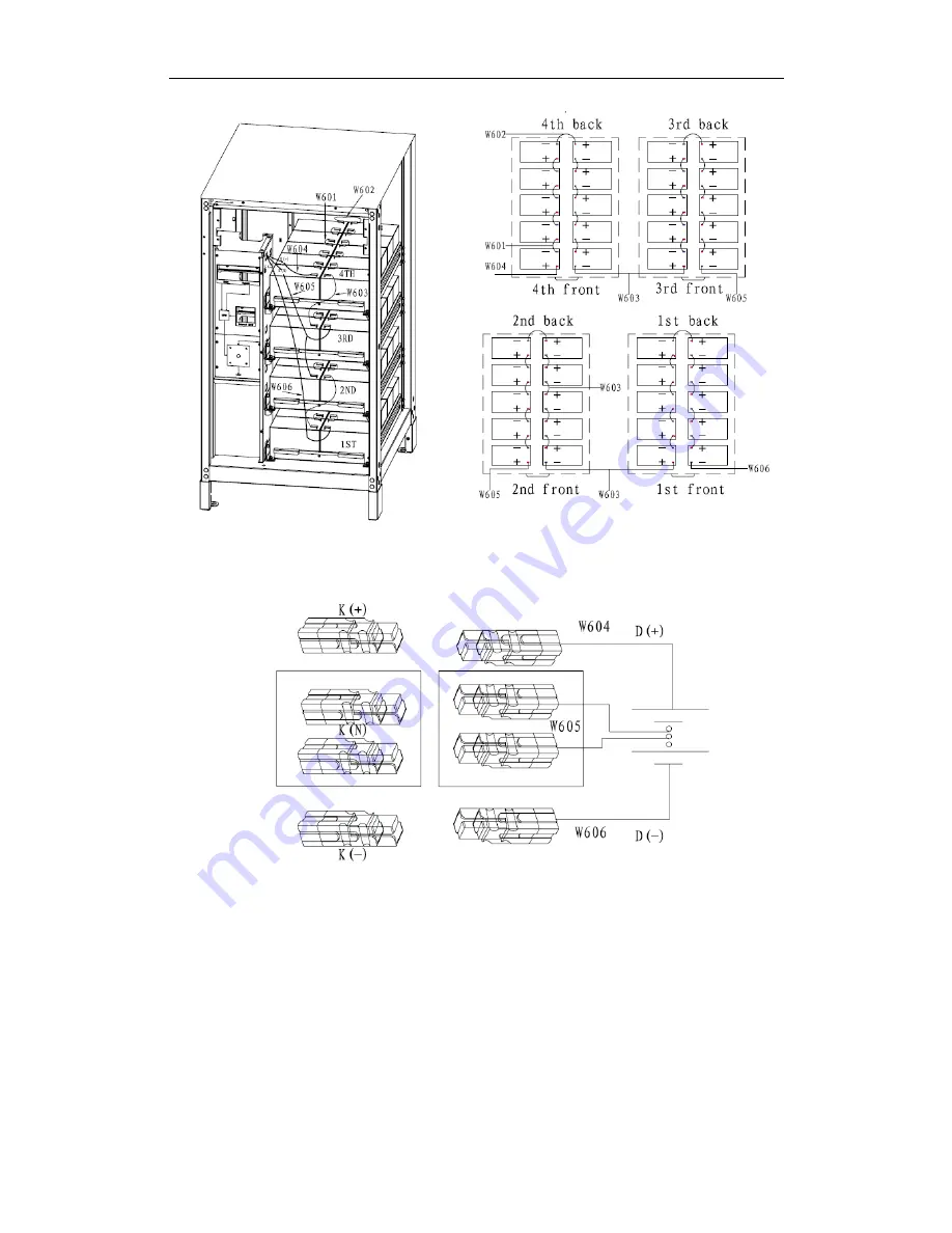
Fig 2-5a Build-in battery connection diagram
The UPS and batteries are connected by Anderson terminals as shown below, according to the mark
of cables, connect cables W404,W405,W406 to K(+),K(N),K(-).
Fig 2-5b Build-in battery connection diagram
2.6 Control and Communication Cable
As shown in fig. 2-6, there are dry contact interfaces (J2-J10), communication interfaces (RS232
interface, 485 interface, and SNMP card interface) and LBS interface.


