background image

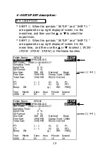
A : Folder Name range: WTA01 to WTA10.
B : Press   or   to select the expect folder number, the

     number consists of " 01 to 10 " (as screen 1).
C : Press   or   continuously at least two seconds can

     skip the numbers faster.
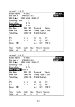
D : Press SHIFT KEY once, the symbol " SHIFT1" will
     appear on up right display, and then press   to entry next

     setting function as screen 2 (Folder Name   File Name).

4-5-2 File Name: Set the file name for SD

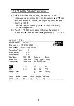
A : The screen will show " NO File " indicator in REC Date
     option when the selected file is new ( as screen 1 ).
B : The screen will show recording date and time in REC
     Date option when the selected file has been recorded
     as screen 2.

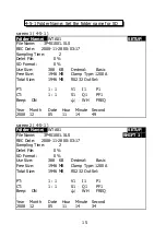
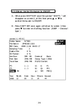
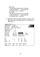
screen 1 ( 4-5-2 )
Folder Name:

WTA03

SETUP

File Name:

3P401001.XLS

REC Date:     NO File
Sampling Time:           2
Delet File:              0 %
SD Format:             0 %
Use Size: 

388   KB

Decimal:       Basic

Free Size: 

1946 MB

Clamp Type: 1200A

Total Size:

1946 MB

RS232 Out Sel:

PT:

1 : 1

V1

I1

P1

CT: 

1 : 1

S1

Q1

PF1

Beep:    ON

  Φ1

WH

FREQ

Year Month

Date

Hour Minute Second

2008 12

05

15

10

55

16

Summary of Contents for LDW-6092K

Page 1: ...a step forward for you into the field of precision measurement Although this POWER ANALYZER is a complex and delicate instrument its durable structure will allow many years of use if proper operating...

Page 2: ...not apply the overload voltage current to the input terminal Remove test leads before open the battery cover Cleaning Only use the dry cloth to clean the plastic case Environment Conditions Installati...

Page 3: ...es measurement 35 5 2 1 3W one phase by three wires measurement 36 5 3 3 3W three phase by three wires measurement 38 5 4 3 4W three phase by four wires measurement 39 5 5 The CT and PT measurement 41...

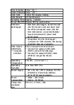
Page 4: ...Mega ohms Safety Standard IEC 1010 CAT III 600V Built in clock and Calendar real time data record with SD memory card sampling time set from 2 to 7200 seconds Just slot in the SD card into the comput...

Page 5: ...ive Power Power factor Phase angle Frequency Wire 1P 2W 1P 3W 3P 3W 3P 4W connections Voltage ranges 10 ACV to 600 ACV auto range Current ranges 0 2 ACA to 1200 ACA auto range manual range Safety IEC1...

Page 6: ...e Excel Integration time for data logger 2 seconds to 7200 seconds the during of setting step are 2 seconds Data Output RS232 computer serial interface USB RS232 Connect the optional USB cable Compute...

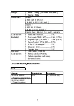
Page 7: ...l 1 PC Included Test Leads TL88 4AT 1 Set 4 PCs Alligator clips TL88 4AC 1 Set 4 PCs Clamp Probe CP 1200 3 PCs AC to DC 9V adapter 1 PC SD card 2 G 1 PC Carrying bag 1 PC Optional USB Cable USB 01 Acc...

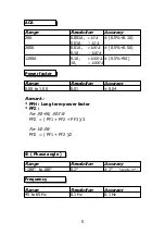
Page 8: ...0 1A 1000 A 0 5 5A 1A 1000 A Power factor Range Resolution Accuracy 0 00 to 1 00 0 01 0 04 Remark PFH Long term power factor PF For 3 4W 3 3W PF PF1 PF2 PF3 3 For 1 3W PF PF1 PF2 2 Phase angle Range...

Page 9: ...wer Range Resolution Accuracy 0 000 to 9 999 KVA 0 001 KVA 1 0 008KVA 10 00 to 99 99 KVA 0 01 KVA 1 0 08KVA 100 0 to 999 9 KVA 0 1 KVA 1 0 8KVA 1 000 to 9 999 MVA 0 001 MVA 1 0 008MVA Reactive Power R...

Page 10: ...SH Range Resolution Accuracy 0 000 to 9 999 KVAH 0 001 KVAH 2 0 008 KVAH 10 00 to 99 99 KVAH 0 01 KVAH 2 0 08 KVAH 100 0 to 999 9 KVAH 0 1 KVAH 2 0 8 KVAH 1 000 to 9 999 MVAH 0 001 MVAH 2 0 008 MVAH...

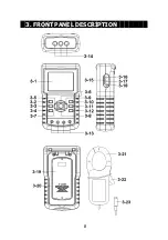
Page 11: ...3 FRONT PANEL DESCRIPTION 8...

Page 12: ...9 REC key button 3 10 A current range key button 3 11 Shift key button 3 12 Setup key button 3 13 Voltage input terminals 3 14 Current probe input sockets 3 15 SD card socket 3 16 RS232 socket 3 17 R...

Page 13: ...t display of screen 1 will show as SD Check along with blinking while inserting SD CARD then disappears after several seconds that indicates the data from SD CARD has been read completed 2 The bottom...

Page 14: ...3 0 0 WH 0 000 KWH SH 0 000KVAH QH 0 000 KVARH FREQ 0 0 Hz AUTO SD 20A 3 4W SEC 2 CT 1 PT 1 Check screen 1 4 2 V12 0 0 V V1 0 0 V A1 0 00 A V23 0 0 V V2 0 0 V A2 0 00 A V31 0 0 V V3 0 0 V A3 0 00 A P...

Page 15: ...a record key for SD CARD 5 HOLD KEY 3 5 Fig 1 Press the key to freeze the display reading 6 BACKLIGHT KEY 3 6 Fig 1 Press the key to switch LCD backlight to ON OFF 7 SETUP KEY 3 12 Fig 1 Press the key...

Page 16: ...C Date 2008 11 28 00 03 17 Sampling Time 2 Delet File 0 SD Format 0 Use Size 388 KB Decimal Basic screen 1 4 4 Free Size 1946 MB Clamp Type 1200A Total Size 1946 MB RS232 Out Sel PT 1 1 V1 I1 P1 CT 1...

Page 17: ...SD CARD SD Format to Format SD CARD fast PT Set the potential transformer from 1 to 1000 CT Set the current transformer from 1 to 600 Beep Set to ON OFF for buzzer Clamp Type Select the Clamp Type to...

Page 18: ...32 Out Sel PT 1 1 V1 I1 P1 CT 1 1 S1 Q1 PF1 Beep ON 1 WH FREQ Year Month Date Hour Minute Second 2008 12 05 11 14 49 screen 2 4 5 1 Folder Name WTA01 SETUP File Name 3P401001 XLS SHIFT 1 REC Date 2008...

Page 19: ...the file name for SD A The screen will show NO File indicator in REC Date option when the selected file is new as screen 1 B The screen will show recording date and time in REC Date option when the s...

Page 20: ...from 001 to 050 Remark When press or 2 sec the setting no will change fast 1P201001 1P2 means one phase by two wires 01 means folder number 001 means file number 1P301001 1P3 means one phase by three...

Page 21: ...3 SD Format 0 4 5 2 Use Size 388 KB Decimal Basic Free Size 1946 MB Clamp Type 1200A Total Size 1946 MB RS232 Out Sel PT 1 1 V1 I1 P1 CT 1 1 S1 Q1 PF1 Beep ON 1 WH FREQ Year Month Date Hour Minute Sec...

Page 22: ...5 3 Folder Name WTA01 SETUP File Name 3P401001 XLS SHIFT 1 REC Date 2008 11 28 00 03 17 Sampling Time 2 Delet File 0 SD Format 0 Use Size 388 KB Decimal Basic Free Size 1946 MB Clamp Type 1200A Total...

Page 23: ...ased then return to screen 1 or else press SETUP KEY in Y or N option to return to screen 1 B Press in screen 1 to enter next setting function Delete File SD Format screen 1 4 5 4 Folder Name WTA01 SE...

Page 24: ...Year Month Date Hour Minute Second 2008 12 05 11 16 45 4 5 5 SD Format Formatting function for SD CARD A The indicator Y or N will appear on right side display of the option while pressing SHIFT KEY...

Page 25: ...I1 P1 CT 1 1 S1 Q1 PF1 Beep ON 1 WH FREQ Year Month Date Hour Minute Second 2008 12 05 11 17 05 screen 2 4 5 5 Folder Name WTA01 SETUP File Name 3P401001 XLS SHIFT 1 REC Date 2008 11 28 00 03 17 Sampl...

Page 26: ...ge fast B Press SHIFT KEY once again will return to screen 1 then press to enter next setting function PT CT screen 1 4 5 6 Folder Name WTA01 SETUP File Name 3P401001 XLS SHIFT 1 REC Date 2008 11 28 0...

Page 27: ...Date Hour Minute Second 2008 12 05 11 19 07 4 5 7 CT Set the Current Transformer A When press SHIFT KEY once the symbol SHIFT1 will disappear as screen 2 at this time press or can adjust to expect CT...

Page 28: ...1 1 V1 I1 P1 CT 1 1 S1 Q1 PF1 Beep ON 1 WH FREQ Year Month Date Hour Minute Second 2008 12 05 11 19 20 screen 2 4 5 7 Folder Name WTA01 SETUP File Name 3P401001 XLS REC Date 2008 11 28 00 03 17 Sampli...

Page 29: ...een 1 then press to enter next setting function BEEP Decimal type screen 1 4 5 8 Folder Name WTA01 SETUP File Name 3P401001 XLS SHIFT 1 REC Date 2008 11 28 00 03 17 Sampling Time 2 Delete File 0 SD Fo...

Page 30: ...Hour Minute Second 2008 12 05 11 19 58 4 5 9 Decimal Type set the Decimal type to Basic or Euro The numerical data structure of SD card is default used the as the decimal for example 20 6 1000 53 But...

Page 31: ...again will return to screen 1 then press to enter next setting function Decimal type Clamp type screen 1 4 5 9 Folder Name WTA01 SETUP File Name 3P401001 XLS SHIFT 1 REC Date 2008 11 28 00 03 17 Samp...

Page 32: ...ut Sel PT 1 1 V1 I1 P1 CT 1 1 S1 Q1 PF1 Beep ON 1 WH FREQ Year Month Date Hour Minute Second 2008 12 05 11 20 18 4 5 10 Clamp Type set the clamp type to 200A or 1200A A When press SHIFT KEY once the s...

Page 33: ...1 1 V1 I1 P1 CT 1 1 S1 Q1 PF1 Beep ON 1 WH FREQ Year Month Date Hour Minute Second 2008 12 05 11 20 18 screen 2 4 5 10 Folder Name WTA01 SETUP File Name 3P401001 XLS REC Date 2008 11 28 00 03 17 Sampl...

Page 34: ...screen 3 C After the selecting is completed press SHIFT KEY continuously at least two seconds again will return to screen 1 and show all the selected items at the same time D Press in screen 1 to ente...

Page 35: ...S 28 2 7 I1 18 Q1 29 3 8 I2 19 Q2 30 WH 9 I3 20 Q3 31 SH 10 P1 21 Q 32 QH 11 P2 22 PF1 33 FREQ screen 3 4 5 11 RS232 OUTPUT SELECT 1 V12 12 P3 23 PF2 2 V23 13 P 24 PF3 3 V31 14 S1 25 PF 4 V1 15 S2 26...

Page 36: ...dition to adjust the numbers and the setting value will also be saved during the adjusting E In the function of setting second press or to adjust numbers at this point the number of second is at a sta...

Page 37: ...nute Second 2008 12 05 12 02 28 4 5 13 When all settings are completed press EXIT KEY to return measuring screen 4 5 14 The descriptions about SD CARD memory space A Use Size To show the space data nu...

Page 38: ...ed name of system will be appeared on bottom left display of screen 2 B 2 Connect the line voltage L1 Vn Neutral to V1 and N terminals of the instrument B 3 Place the conductor of CP 1200 A1 to A1 as...

Page 39: ...0 A P 1 0 000KW P F 1 0 00 S 1 0 000KVA P F H 0 00 Q 1 0 000KVAR 1 0 0 W H 0 000KWH S H 0 000KVAH Q H 0 000KVARH F R E Q 50 1 Hz AUTO 20A 1 2W SEC 2 CT 1 PT 1 5 2 1 3W one phase by three wires measure...

Page 40: ...and A2 as screen 1 B 4 Connect the outputs of clamp meter CP 1200 A1 CP 1200 A2 to A1 and A2 terminals of the instrument B 5 The related measuring factors will be appeared on display about the instru...

Page 41: ...om left display of screen 2 B 2 Connect the line voltage L1 L2 and L3 to V1 V2 and V3 terminals of the instrument B 3 Place the conductor of CP 1200 A1 CP 1200 A2 CP 1200 A3 hook to A1 A2 A3 as screen...

Page 42: ...A 2 0 00 A V 3 1 0 0 V A 3 0 00 A P 0 000 KW S 0 000 KVA Q 0 000 KVAR PF 0 00 P F H 0 00 WH 0 000 KWH SH 0 000 KVAH QH 0 000 KVARH FREQ 50 0 Hz AUTO 20A 3 3W SEC 2 CT 1 PT 1 5 4 3 4W three phases by f...

Page 43: ...mp meter CP 1200 A1 CP 1200 A2 CP 1200 A3 to A1 A2 A3 terminals of the instrument B 5 The related measuring factors will be appeared on display about the instruction of factor please refer appendix 1...

Page 44: ...play of screen 2 B 2 Connect the line voltage L1 L2 L3 and Vn to V1 V3 and N terminals of the instrument B 3 Place the conductor of CP 1200 A1 CP 1200 A2 CP 1200 A3 hook to A1 A2 A3 as screen 1 B 4 Co...

Page 45: ...0 000 KW S3 0 000 KVA Q3 0 000 KVAR P 0 000 KW S 0 000 KVA Q 0 000 KVAR PF1 0 00 PF2 0 00 PF3 0 00 PF 0 00 PFH 0 00 1 0 0 2 0 0 3 0 0 WH 0 000 KWH SH 0 000 KVAH QH 0 000 KVARH FREQ 0 0 Hz AUTO 20A 3...

Page 46: ...P3 0 000 KW S3 0 000 KVA Q3 0 000 KVAR P 0 000 KW S 0 000 KVA Q 0 000 KVAR PF1 0 00 PF2 0 00 PF3 0 00 PF 0 00 PFH 0 00 1 0 0 2 0 0 3 0 0 WH 0 000 KWH SH 0 000 KVAH QH 0 000 KVARH FREQ 0 0 Hz AUTO Cha...

Page 47: ...2 0 0 3 0 0 WH 0 000 KWH SH 0 000 KVAH QH 0 000 KVARH FREQ 0 0 Hz AUTO REC 20A 3 4W SEC 2 CT 1 PT 1 9 screen 2 5 6 B V12 0 0 V V1 0 0 V A1 0 00 A V23 0 0 V V2 0 0 V A2 0 00 A V31 0 0 V V3 0 0 V A3 0 0...

Page 48: ...000 KW S3 0 000 KVA Q3 0 000 KVAR P 0 000 KW S 0 000 KVA Q 0 000 KVAR PF1 0 00 PF2 0 00 PF3 0 00 PF 0 00 PFH 0 00 1 0 0 2 0 0 3 0 0 WH 0 000 KWH SH 0 000 KVAH QH 0 000 KVARH FREQ 0 0 Hz AUTO 20A 3 4W...

Page 49: ...B When hold A RANGE KEY down at least for 2 seconds will change MANUAL to AUTO as show on bottom left display of screen 4 V12 0 0 V V1 0 0 V A1 0 00 A V23 0 0 V V2 0 0 V A2 0 00 A V31 0 0 V V3 0 0 V...

Page 50: ...WH 0 000 KWH SH 0 000 KVAH QH 0 000 KVARH FREQ 0 0 Hz MANU 1200A 3 4W SEC 2 CT 1 PT 1 screen 2 5 9 V12 0 0 V V1 0 0 V A1 0 00 A V23 0 0 V V2 0 0 V A2 0 00 A V31 0 0 V V3 0 0 V A3 0 00 A P1 0 000 KW S...

Page 51: ...0 KVARH FREQ 0 0 Hz AUTO 20A 3 4W SEC 2 CT 1 PT 1 screen 4 5 9 5 11 The LOWBAT screen as show on lower right display of the following screen V12 0 0 V V1 0 0 V A1 0 00 A V23 0 0 V V2 0 0 V A2 0 00 A V...

Page 52: ...t Power VA Q Total Reactive Power VAR PF1 PF2 PF3 Power Factor of each phase PE Total Power Factor PFH Long Term Average Power Factor WH SH 1 2 3 Phase Angle of each phase WH Watt Hour SH Apparent Pow...

Page 53: ...1 When Display show the LOWBAT indicator ref 5 10 page 48 it should change the batteries 2 open the Battery Cover 3 19 Fig 1 away from the instrument and remove the battery 3 Replace with batteries DC...

Page 54: ...an be utilized to the user s specific application A RS232 lead with the following connection will be required to link the instrument with the PC serial input Meter PC 3 5 mm jack plug 9W D Connector C...

Page 55: ...HR C6 KVAR D7 KVAR Hr B6 KACV C7 MVAR D8 MVAR Hr B7 MACV C8 GVAR D9 GVAR Hr B8 KACA C9 TVAR E0 TVAR Hr B9 MACA D0 MW Hr D10 Polarity 0 Positive 1 Negative D9 Decimal Point DP position from right to t...

Page 56: ...into the SD card adapter then connect the SD card adapter into the computer 3 Power ON the computer and run the EXCEL software Down load the saving data file for example the file name 3P401001 XLS 1P...

Page 57: ...EXCEL data screen 2 for example EXCEL data screen 3 for example EXCEL data screen 4 for example 54...

Page 58: ...EXCEL data screen 5 for example EXCEL data screen 6 for example EXCEL graphic screen 1 for example 55...

Page 59: ...EXCEL graphic screen 2 for example EXCEL graphic screen 3 for example 56...

Page 60: ...L graphic screen 5 for example 9 PATENT The SD card installation for handheld instruments and the SD card data format structure Data to EXCEL file format already patent pending in the following countr...

Page 61: ...power consumption can be monitored This usually means the currents should be drawn from a single power source the transformer Question If it can do this what settings should be used ie 3P4W or 1P3W et...

Page 62: ...10 THE ADDRESS OF AFTER SERVICE CENTER 58 0905 DW6092 XLS www esis com au Ph 02 9481 7420 Fax 02 9481 7267 esis enq esis com au Distributed and supported by...

Reviews: