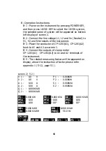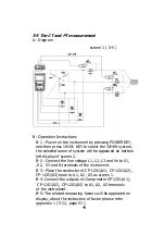
B: Operation Instructions:
B-1 : Power on the instrument by pressing POWER KEY,
and then press 1
Φ
3
Φ
KEY to select the 3
Φ
4W system,
the selected name of system will be appeared on bottom
left display of screen 2.
B-2 : Connect the line voltage L1, L2, L3 and Vn to
V1, V2, V3 and N terminals of the instrument.
B-3 : Place the conductor of CP-1201(A1), CP-1201(A2)
、
CP-1201(A3) hook to A1, A2, A3 as screen 1.
B-4 : Connect the outputs of clamp meter
CP-1201(A1), CP-1201(A2), CP-1201(A3) to
A1
、
A2
、
A3 terminals of the instrument.
B-5 : The related measuring factors will be appeared
on display, about the instruction of factor please refer
appendix 1 ( 5-12, page 51 ).
screen 2 ( 5-4 )
V12:
0.0 V
V1:
0.0 V
A1:
0.00
A
V23:
0.0 V
V2:
0.0 V
A2:
0.00
A
V31:
0.0 V
V3:
0.0 V
A3:
0.00
A
P1:
- 0.000 KW
S1:
0.000 KVA
Q1:
- 0.000 KVAR
P2:
- 0.000 KW
S2:
0.000 KVA
Q2:
- 0.000 KVAR
P3:
- 0.000 KW
S3:
0.000 KVA
Q3:
- 0.000 KVAR
P
Σ
- 0.000 KW
S
Σ
:
0.000 KVA
Q
Σ
:
- 0.000 KVAR
PF1:
- 0.00
PF2:
- 0.00
PF3:
- 0.00
PF
Σ
:
0.00
PFH:
0.00
Φ
1:
- 0.0°
Φ
2:
- 0.0°
Φ
3:
- 0.0°
WH:
0.000 KWH
SH:
0.000 KVAH
QH:
0.000 KVARH
FREQ:
0.0
Hz
CP1201
20A
3
Φ
4W
SEC: 2 CT: 1
PT: 1
43


