Setup
and Assembly
Page 5-18
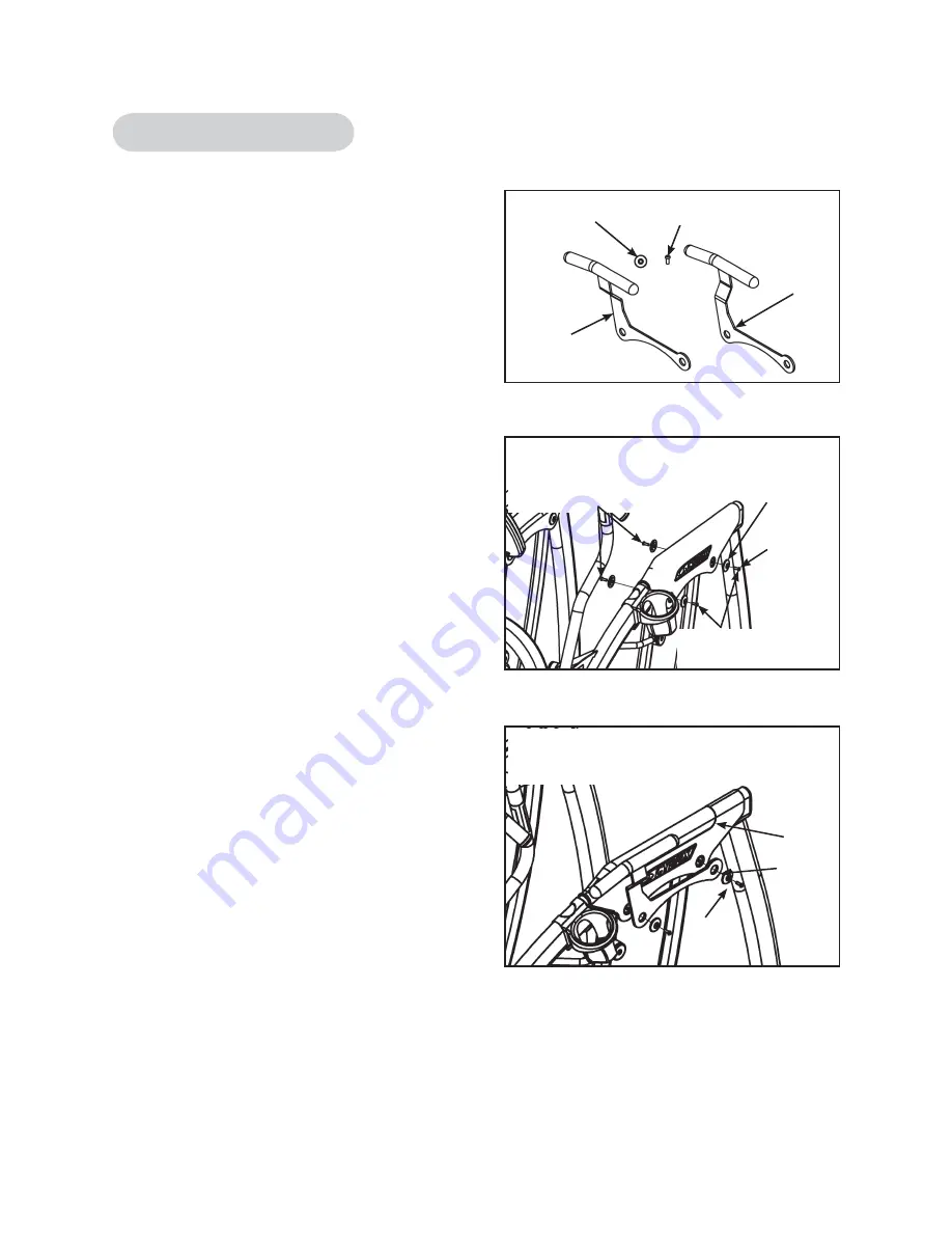
Figure 1
Figure 2
C
Figure 3
D
A
B
Pivot Shaft
Retainer
BHSCS
NOTE:
This side is exploded
for diagram purposes. These
two screws do not need to
be removed.
D/E
C
A
NOTE:
Remove these
two
screws.
NOTE:
Verify that this part of the handle
is facing toward the front of the
Arc
Trainer.
Cybex Arc Trainer 630A Owner’s Manual
NOTE:
(1) Standard for Total Access units.
(2) Optional for standard units.
Tools Required
• 7/32” Allen wrench (2)
1. Please read instructions thoroughly
before
beginning.
2. Verify kit contents. See Figure 1.
A.
Left hand side handle, (1), 610A-211
B.
Right hand side handle, (1), 610A-212
C.
Pivot shaft retainer, (4), 610A-377
D.
BHSCS .375-16 x 1.00 SS, (4), HX700417
E.
Loctite, (1), YA000201 (not shown)
3.
Install the handles.
A.
Using two 7/32” Allen wrenches, remove
two of the four BHSCS securing one of the
pivot
covers.
NOTE:
Remove one of the
two screws in the front and one of the two
in the back. The other two screws will
remain loctited into the shaft.
See Figure 2.
B.
If an inside screw broke from the loctite
and an outside screw did not, then remove
the shaft and reinstall it on the other side
so that the handle bracket can be installed
on the outside part of the frame.
C.
Place a drop of loctite (E) on two new
BHSCS. Place another drop of loctite in
the shaft (where each SHCS will be
tightened
into).
D.
Install the side handle using the two
retainers and BHSCS. Tighten both screws
securely. See
NOTE:
Install the handle
bracket so that the handle is toward the
front.
Figure 3.
E.
Repeat steps 3A through 3D to install the
other side handle.
F.
Test the unit to verify proper operation.
Side Handles - Optional
Summary of Contents for Arc 630A
Page 2: ......
Page 4: ......
Page 7: ......
Page 8: ......
Page 18: ...Safety Page 1 10 Cybex Arc Trainer 630A Owner s Manual This page intentionally left blank ...
Page 44: ...This page intentionally left blank Cybex Arc Trainer 630A Owner s Manual Operation Page 3 24 ...
Page 86: ......
Page 87: ......


